V Tune Pro TV/ FM Tuner Closed Captioning, OSD, RS-232, IR, Contact Closure Control Installation and Operations Manual Manual Rev: 050224 Firmware Rev: 1.25 205 Commercial Court Morganville, NJ 07751 Voice: (732) 591-5800 Fax: (732) 591-5801 www.auroramultimedia.
Table of Contents Product Description ................................1 Warning ................................................. 2 Unpacking ............................................ 2 Installation ............................................. 2 System Overview ................................... 2 Remote Control .................................... 3 Front Panel ............................................ 4 Setup Mode . ........................................ 5 Specifications .......................
1.0 Product Description The VTune Pro is a 181-channel Closed Caption TV Tuner with composite video out. Built in OSD allows for on-screen channels and volume. The VTune Pro allows up to 999 units to be connected together via 1 RS-232 port and the advanced addressable RS-232 command set. It is a perfect low cost TV or FM Tuner for any AV System. The VTune is also a great compliment to stand alone display devices such as Plasma, LCD, and CRT displays.
Caution: Static (Still) pictures will cause “burn in” on certain types of displays and may 2.0 damage the display device. When using static images, reducing brightness and/or contrast can help reduce the risk of damage to the display device. Refer to the display’s owners and technical manual about additional precautions. 3.
6.0 Remote Control Using the Aurora IRC-7 Remote Control POWER V Tune Pro F1 1 F2 F3 MUTE 2 3 4 5 CC EDS AUDIO 8 9 10 TV VOL 6 FM 13 11 15 12 17 MENU INFO 18 19 14 CH 7 1 2 3 4 5 6 7 8 9 20 23 26 21 24 27 SET 25 28 LAST 0 31 P1 P2 P3 32 33 34 P4 P5 P6 35 36 37 P7 P8 P9 38 39 40 P10 P11 P12 41 42 43 Presets Source Selection 11. TV INPUT - Selects the TV Antenna as the Main source 12.
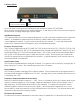
7.0 Front Panel The VTune Pro front panel is simple but very effective. The orange seven segment display shows the current TV channel selected for Main or PiP channel. Ch+: Increments the TV or FM channel up Ch-: Decrements the TV or FM channel down Vol+: Raises the volume. Front LED display will show v 52 if the level is at 52 for example. Times out after 3 sec. Vol-: Lowers the volume. Front LED display will show v 52 if the level is at 52 for example. Times out after 3 sec.
8.0 Setup_Mode Add/Delete Channels. LED is lit if the channel is added. LED will be lit if in setup mode. To access setup mode press the following remote sequence quickly: SET, UP, DOWN When in setup mode the right most decimal will be lit. To exit setup mode cycle the power using the power button or unplug and plug the power cable. Add/Delete Channels If TV is selected then the current channel will appear. The left most decimal will be lit if the channel is added.
.0 Setup_Mode (Continued) press the FM button. Use the volume +/- to adjust the level. Switch back and forth between a tuned TV channel and a tuned FM channel until it sounds close to the same level. The mute button will toggle the auto FM mute function. If the station is weak the auto mute will turn off the audio instead of having to listen to static. This feature may be disabled to listen to weaker stations with static. Baud Rate P1-P5 buttons allow the selection of the VTune Baud rate.
.0 Specifications RF Tuner (North America) Input Connector : 'F' type female TV Frequency Range : 55.25 to 801.25 MHz, 31.25 or 62.5KHz fine tune FM Frequency Range : 76.00 to 108.00 MHz, 50KHz fine tune Demodulation: Quasi-Split Sound concept RF Tuner (International) Input Connector : 'IEC' type female TV Frequency Range : 48.25 to 855.25 MHz, 31.25/50.0, or 62.5KHz fine tune FM Frequency Range : 76.00 to 108.
.0 Control Port RS232 - Pins 1,3,5 Pin 1 - Ground Pin 3 - TX Pin 5 - RX Contact Closure - Pins 1,2,4,6 Pins 1,2: TV Pins 1,4: Channel + Pins 1,4,6: FM Pins 1,2,4: Volume + Pins 1,6: Channel Pins 1,2,6: Volume - 11.0 RS-232 Protocol Baud Rate: Factory Default 9600 8N1 but can be changed up to 115200 (See Setup Section). Note: Protocol below is as of firmware version 1.25 New commands will be available on future revisions to give more discrete full featured commands.
.0 RS-232 Protocol (Continued) !KEY_6 !KEY_7 !KEY_8 !KEY_9 !KEY_SET !KEY_P1 !KEY_P2 !KEY_P3 !KEY_P4 !KEY_P5 !KEY_P6 !KEY_P7 !KEY_P8 !KEY_P9 !KEY_P10 !KEY_P11 !KEY_P12 !KEY_VOL+ !KEY_VOL- !KEY_MUTE !KEY_PWR !KEY_F1 !KEY_F2 !KEY_F3 !KEY_TV !KEY_FM !KEY_MENU !KEY_INFO !KEY_CC !KEY_EDS !KEY_AUDIO !PWRON !PWROFF ?PWR !VOLxx ?VOL ?MCH !MCHxxx ?MIN !FCHxxxx
Bits D4-D1 (AFC4-AFC1) Read the 4 bits separate of the other bits for easy use. eg. (afc & 0x1E) then shift the bits 1 place to the right. This will give you a value of 0x00 to 0x0F. Follow the chart below to determine the signal. Bit4 0 0 0 0 0 0 0 0 1 1 1 1 1 1 1 1 Bit3 1 1 1 1 0 0 0 0 1 1 1 1 0 0 0 0 Bit2 1 1 0 0 1 1 0 0 1 1 0 0 1 1 0 0 Bit1 1 0 1 0 1 0 1 0 1 0 1 0 1 0 1 0 -187.5kHz -162.5kHz -137.5kHz -112.5kHz -87.5kHz -62.5kHz -37.5kHz -12.5kHz +12.5kHz +37.5kHz +62.5kHz +87.5kHz +112.5kHz +137.
12.0 Connector Specifications DC 2.
13.0 Troubleshooting TV Tuner Random noise in video image - Check antenna position or cable connection. Weak signals can cause noise. Use of an RF Signal amplifier may help. Check the TV Source setting in the menu for proper selection between broadcast, cable, IRC, and HRC. White noise - Check antenna position or cable connection. Check the TV Source setting in the menu for proper selection between broadcast, cable, IRC, and HRC. Hum on all channels - Poor grounding will cause this problem.
14.0 Upgrading Firmware 1) Download latest copy of Flash123 from www.auroramultimedia.com under the VTune Pro product section. 2) Download the latest version of firmware. 3) Install Flash123 on a Windows 2000 or better machine. 4) With the power cord unplugged connect the 6 pin Mini Din to 9 pin RS232 cable between the Control port of the VTune Pro and the Com port of the PC. If you do not have a cable the help menu of Flash123 has the pin out.
Limited Lifetime Warranty Aurora Multimedia Corp. (“Manufacturer”) warrants that this product is free of defects in both materials and workmanship for the product lifetime as defined herein for parts and labor from date of purchase. This Limited Lifetime warranty covers products purchased in the year of 2003 and after. Product lifetime is defined as 7 years from discontinuance of product. Motorized mechanical parts (Hard Drives, DVD, etc), remotes and cables are covered for a period of 1 year.
FCC Part 15 Statement RADIO AND TELEVISION INTERFERENCE This equipment has been tested and found to comply with the limits for a Class B digital device, pursuant to Part 15 of the FCC rules. These limits are designed to provide reasonable protection against harmful interference in a residential installation. This equipment generates, uses and can radiate radio frequency energy and, if not installed and used in accordance with the instructions, may cause harmful interference to radio communications.