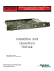
TVP-1000 Video Processor, Scaler, Switcher, Integrated TV Tuner with Hi-Resolution Picture-in-Picture Installation and Operations Manual Manual Rev: 030401 Firmware Rev: 1.30 and above 205 Commercial Court Morganville, NJ 07751 Voice: (732) 591-5800 Fax: (732) 591-5801 www.auroramultimedia.
Table of Contents Product Description ................................1 Warning ................................................. 2 Unpacking ............................................ 2 Installation ............................................. 2 Pioneer Setup ........................................ 4 System Overview ................................... 5 Remote Control .................................... 6 On Screen Display (OSD) ....................... 8 Specifications ...............................
1.0 Product Description The TVP-1000 is an integrated Scaler, TV Tuner, and Switcher capable of Hi-Res PiP. The TVP1000 provides enhanced functionality to Pioneer plasmas for a variety of applications including conference rooms, boardrooms, video conferencing, training facilities, broadcast and video production, home entertainment and much more. The TVP-1000 and the Pioneer plasma make the perfect combination. + Features ? Video Processor, Scaler, Switcher.
2.0 Warning: The TVP-1000 is an ELECTROSTATIC SENSITIVE unit. Please observe precautions in handling. 2.1 Caution: Static (Still) pictures will cause plasma “burn in” and may damage the plasma display. Avoid prolonged usage of the PiP and On Screen Display. When using static images, reducing brightness and/or contrast can help reduce the risk of damage to the plasma. Refer to the Pioneer owners and technical manual about additional precautions and use with expansion cards. 3.
4.0 Installation (continued) For RS-232 Control use the provided 6 pin mini DIN cable and connect it to the Pioneer plasma Combination Out Port. Video/S-Video Input (DVD, VCR, etc.) Antenna Input (Cable TV, etc.) RGB / YPbPr Input (Computer, Component Sources, etc.
5.0 Pioneer Plasma Setup 1) Turn the main power switch located underneath the plasma on. The Plasma should be in standby (Solid Red LED on Front). With the Pioneer remote press the Menu button and then press the Standby button within 3 seconds (Do not hold buttons down together). The plasma will power on and should read “INTEGRATOR MENU” at the top of the screen. 2) Select Input 3 using the Pioneer remote button 3. 3) OPTION TAB BAUD RATE: Change to 9600BPS (factory default is 4800) ID NO.
6.0 System Overview The vast amount of features in the TVP-1000 can seem overwhelming at first. As you will see it is pretty easy to catch on once explained. Think of the TVP-1000 as a separate device living inside the Plasma with its own On Screen Display (OSD) and input connections. Once input 3 on the Plasma is selected it becomes show time for the TVP-1000. Using the 47 button full featured remote many of the functions can be accessed directly.
7.
7.0 Remote Control (continued) Note: TVP-1000 functions will operate only when TVP-1000 button is pressed. Plasma functions will operate only when Plamsa button is pressed or if in mixed mode when the TVP-1000 button is pressed. 1. TVP-1000 - Selects the TVP-1000 to be controlled from the remote 2. Plasma - Selects the Plasma to be controlled from the remote 3. POWER - Controls power for the Plasma 4.
8.0 On Screen Display (OSD) 1. The On Screen Display is activated with the “Menu” button. 2. The OSD is removed if the “Menu” key is again pressed. 3. Pressing the “Menu key returns to the previous menu level. All menus initially mark the first menu item. 8.1 OSD MAIN MENU The first menu column is a set of icons displayed vertically within the OSD. Each menu item is used to navigate to a submenu, which is displayed when the “Select” key is pressed.
On Screen Display (continued) 8.2.2 BRIGHTNESS Activates slider to adjust picture brightness. 8.2.3 SATURATION Activates slider to adjust color saturation. (This item is disabled when input is RGB.) 8.2.4 HUE Activates slider to adjust hue. (This item is disabled when input is RGB.) 8.2.5 H SHARPNESS Activates slider to adjust horizontal sharpness. This value will be lost when a new source is selected or the power is cycled. The Sharpness is processed automatically based on resolution and picture size. 8.2.
On Screen Display (continued) 8.3.6 V POSITION Activates slider to adjust vertical position. 8.4 INPUT SETUP The Input Setup menu contains the sub-menu for input signal selection and input format selection. Both MAIN and PiP channel can map to any one of the following video input. However, there are restrictions based on the board configuration. The chart below shows the valid input combinations.
On Screen Display (continued) 8.4.3 MAIN FORMAT Allows the user to manually override the auto input detection. The firmware detects the input format automatically and converts it to selected display format. INPUT SETUP MAIN INPUT PiP INPUT MAIN FORMAT PiP FORMAT DVI/RGB MODE ADC CLOCK ADC PHASE AUTO ADJUST TV RGB AUTO AUTO NORM 1350 10 8.4.4 PiP FORMAT Allows the user to manually override the auto input detection.
On Screen Display (continued) 8.5 DISPLAY SETUP The display setup menu contains the sub-menu for output display timing and display format selection. 8.5.1 TIMING The 1920x1080i is the default hardware display timing but 720p can be selected as well. 1080i is best for overall features and PC signals while the 720p mode tends to be sharper and good for video sources. 8.5.2 FORMAT The output display format is defaulted to 16:9 EXPAND.
On Screen Display (continued) 8.6.3 SOURCE / COUNTRY (PAL / SECAM Version) There are three choices for TV sources: BCST (broadcast), CATV(cable), IRC and HRC. The default setting is CATV. If this unit is a PAL / SECAM version then there is a place for Country code. TV SETUP MAIN PiP #01 TV SOURCE CH 004 ADD CH 027 CATV TV SETUP MAIN PiP #01 COUNTRY CH 004 ADD CH 027 UK 8.7 PiP SETUP The PiP setup menu is used to subdivide the screen into a pre-defined set of windows.
On Screen Display (continued) 8.7.1.2 TILE MODE The tile mode allows the user to see multiple PiP windows. The most common way to use tile mode is TV channel browsing. Each PiP window has a unique TV channel number (section 8.6.2 PiP) and the display is updated every second by moving the active PiP window sequentially. The TV tuner frequency is changed to the selected channel for each corresponding PiP window. Since the reference board has only one TV tuner, MAIN window can not watch TV in real time.
On Screen Display (continued) 8.9 MISCELLANEOUS MISCELLANEOUS Film mode OSD H position OSD V position Reset - no System info - AUTO1 8.9.1 FILM MODE The film detection switches between VT, AFM, GFX, and SM automatically. This selection allows for manual selection of the processing modes. 8.9.2 OSD POSITION Allows the user to move OSD to different position on the screen. After the position is selected by “<” and “>” keys, the OSD can be further adjusted in both (V) vertical and (H) horizontal directions.
9.0 Specifications Supported Video Input Timing Input Format Horiz. Freq. (KHz) Vertical Freq. (Hz) Active Resolution (Pixels x Lines @ Field/Frame Rate, Hz) Total (Pixels x Lines) Pixel Clock (MHz) 525/60 NTSC, ITU-R BT601-5, RS-170M 15.75/1.001 60.0/1.001 720x480 @ 59.94 i 858x525 13.500 525/60 NTSC, CCIR 656 15.75/1.001 60.0/1.001 720x480 @ 59.94 p 858x525 27.000 625/50 PAL/SECAM, ITU-R BT601-5 15.625 50.000 720x576 @ 50.00 i 864x625 13.500 625/50 PAL/SECAM, CCIR 656 15.625 50.
10.0 Control Port RS232 - Pins 1,3,5 Note: Pin 2 must be disabled with jumper J9 removed (factory default) Pin 1 - Ground Pin 3 - TX Pin 5 - RX Contact Closure - Pins 1,2,4,6 Note: Pin 2 must be enable with jumper J9 on TVP-1000 Pins 1,2: PiP Swap Pins 1,4: Channel + Pins 1,6: Channel Pins 1,4,6: PiP On/Off Pins 1,2,4,6: PiP Move 10.1 RS-232 Protocol Baud Rate: 9600 8N1 Note: Protocol below is as of firmware version 1.
10.1 RS-232 Protocol (Continued) !KEY_MVID !KEY_MSVID !KEY_MRGB !KEY_MYPBPR !KEY_PTV !KEY_PVID !KEY_PSVID !KEY_PRGB !KEY_PYPBPR !OSDON !OSDOFF ?OSD !FLBOX !FPBOX !FPBXST !FPAN !FEXP !FL1.66 !FL1.78 !FL1.85 !FL2.00 !FL2.
10.1 RS-232 Protocol (Continued) ?PIN ?PHV ?PMD PiP Input Query responds with ~PVID or ~PSVID or ~PTV or ~PRGB or ~PYPBPR PiP Single Mode Horz and Vert location Query responds with ~PHxxxVxxx xxx= 000 to 100 Hxxx is Horizontal Position Vxxx is Vertical Position PiP Mode Query responds with ~POFF or ~PONE or ~PSBS or ~PPAP or ~PT1+4 or ~PT1+12 or ~PT0+16 Use the commands below only if you are experienced with the operation of the XTune.
10.1 RS-232 Protocol (Continued) Hello World The above is to show the display area (grey) with the text Hello World in Green. The white outline is a representation of where the 15 x 30 area may be position based on the delay commands. A white border does not appear on the actual screen. General Info Unless otherwise noted all valid commands are echoed back if properly received.
11.
12.0 Troubleshooting TV Tuner Random noise in video image - Check antenna position or cable connection. Weak signals can cause noise. Use of an RF Signal amplifier may help. Check the TV Source setting in the menu for proper selection between broadcast, cable, IRC, and HRC. White noise - Check antenna position or cable connection. Check the TV Source setting in the menu for proper selection between broadcast, cable, IRC, and HRC. Hum on all channels - Poor grounding will cause this problem.
13.0 Frequently Asked Questions It is generally a good idea to make certain the latest firmware from the Aurora site is loaded into the unit. To find out what revision the TVP-1000 firmware is, go to miscellaneous, then system info under the TVP-1000 menu. Compare it with the web. Updating the latest rev will assure any past bugs are fixed or enhance features are added. Q: Why is the screen green? A: Pioneer Integrator menu is not setup properly.
13.0 Frequently Asked Questions Continued Q: I can not get an image out of my Satellite receiver. A: Some receivers output 1080i and 720p as RGBHV. The current version of TVP-1000 firmware only supports video resolution on the YPbPr. Q: Is there an easy way to do translucent PiP. A: With single PiP selected use the up and down arrows on the remote to control how much the image is blended. Q: PiP on/off button on the remote does not work properly.
14.0 Upgrading Firmware 1) Download latest copy of Flash123 from www.auroramultimedia.com under the TVP-1000 product section. 2) Download the latest version of firmware. 3) Install Flash123 on a Windows 2000 or better machine. 4) With the Plasma off connect the 6 pin Mini Din to 9 pin RS232 cable between the Control port of the TVP-1000 and the Com port of the PC. Do not try to upgrade firmware going through the Plasma RS-232. If you do not have a cable the help menu of Flash123 has the pin out.
Limited Lifetime Warranty Aurora Multimedia Corp. (“Manufacturer”) warrants that this product is free of defects in both materials and workmanship for the product lifetime as defined herein for parts and labor from date of purchase. This Limited Lifetime warranty covers products purchased in the year of 2003 and after. Product lifetime is defined as 7 years from discontinuance of product. Motorized mechanical parts (Hard Drives, DVD, etc) and cables are covered for a period of 1 year.
FCC Part 15 Statement RADIO AND TELEVISION INTERFERENCE This equipment has been tested and found to comply with the limits for a Class B digital device, pursuant to Part 15 of the FCC rules. These limits are designed to provide reasonable protection against harmful interference in a residential installation. This equipment generates, uses and can radiate radio frequency energy and, if not installed and used in accordance with the instructions, may cause harmful interference to radio communications.