USERS GUIDE ASP-44 4x4 HDMI Matrix i Manual Number: 130102
User Guide SAFETY INSTRUCTIONS Please review the following safety precautions. If this is the first time using this model, then read this manual before installing or using the product. If the product is not functioning properly, please contact your local dealer or Aurora for further instructions. The lightning symbol in the triangle is used to alert you to the presence of dangerous voltage inside the product that may be sufficient to constitute a risk of electric shock to anyone opening the case.
User Guide TABLE OF CONTENTS PACKAGE CONTENTS .............................................................................................................2 INTRODUCTION........................................................................................................................3 About ..................................................................................................................................................... 3 Features .....................................................
User Guide PACKAGE CONTENTS Please make sure the following items are included within your package. Contact your dealer if any items are missing or damaged. • ASP-44 Matrix • Remote • IEC Power Cord x 1 • 2 Rack Mount Angle Brackets • 5V Power Supply • Owners Manual Note: Go to www.auroramultimedia.
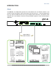
User Guide INTRODUCTION About The ASP-44™ 4x4 HDMI Matrix provides the most flexible and cost effective solution in the market to route high definition video sources plus multi-channel (up to 7.1 channel) digital audio from any of the four HDMI sources to the any four displays at the same time. This solution is well suited for use in home theater, conference room presentation systems, or other similar setting or application.
User Guide Features State-of-the-art Silicon Image (Founder of HDMI) chipset embedded for utmost compatibility and reliability HDMI 3D and Deep Color compliant HDCP compliant Allows any source to be displayed on multiple displays at the same time Allows any HDMI display to view any HDMI source at any time Supports 7.
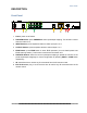
User Guide DESCRIPTION Front Panel 1 2 3 4 5 6 7 8 1. Power: power on/off switch 2. PREVIEW Button: press PREVIEW to watch input/output mapping. This function is active when the button is lit. 3. INPUT Buttons: press respective button to select input port 1 to 4 4. OUTPUT Buttons: press respective button to select output 1 to 4 5. EDID Button: press EDID button to enter EDID operation (for more detail please see EDID Learning section). This function is active when the button is lit. 6.
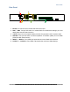
User Guide Rear Panel 1 3 4 2 5 6 1. RS-232: For channel control via RS-232 serial control port 2. SW1 – SW4: Two-pin DIP switch for manual EDID and audio/video settings (for more detail please see DIP Switch section) 3. +5V DC: Plug in the 5V 6A power supply unit with C5-type power cord to a power outlet 4. SW Main: Four-pin DIP switch for normal operation or firmware update (for more detail please see DIP Switch section) 5.
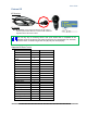
User Guide External IR IR Receiver IR Sockets EXT IR Receiver: plug in the IR receiver to the IR socket on the front panel of the ASP-44 to receive all IR command signals from the IR remote control You can buy any IR receiving cable in the open market that is compatible to the definition of the IR sockets for the matrix if necessary for replacement use. However, in some cases, IR cables longer than 2m (6ft) may not work properly.
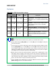
User Guide EDID SETUP Dip Switch SW1-SW4 for EDID & audio/video settings DIP Switch Position Pin 1 Pin 2 OFF [] OFF [] Video Up to 1080p Audio Description 2 Default Mode – Up to 1080p & surround sound audio output up to 7.
User Guide SW Main for firmware update (for technical support only) DIP Switch Position Pin 1 Pin 2 Pin 3 Pin 4 6 OFF[] OFF[] ON[] OFF[] 7 ON[] ON[] OFF[] OFF[] Normal Operation Mode Firmware Update Mode Note 6 7 Factory default for SW Main is pin 1 at OFF [], pin 2 at OFF [], pin 3 at ON [], and pin 4 at OFF [].
User Guide OPERATION Front Panel Manual Switching 1. Press the INPUT button on the front panel to select input source port, which will be lit once selected. 2. Press the OUTPUT buttons on the front panel to select output display ports, which will be lit once selected, to display HDMI signal from selected input port. Front Panel Preset Switching Load presets Step 2 Step 1 & 3 1. Press the LOAD button in the PRESETS menu on the front panel and the LED will turn on. 2.
User Guide 1. Press the SAVE button in the PRESETS menu on the front panel and the LED will turn on. 2. Select the preset profile number and save the current mapping profile to the memory. 3. Press the SAVE button to execute the setting. After loading procedure, the LED will turn off. PREVIEW presets Step 3 Step 2 & 4 Step 1 & 4 1. Press the PREVIEW button on the front panel. 2. Press the LOAD button. 3. Select the preset profile number to load the corresponding mapping and press the respective button.
User Guide Remote Control POWER Power on/off Fn Function key INPUT 1 HDMI input port 1 INPUT 2 HDMI input port 2 INPUT 3 HDMI input port 3 INPUT 4 HDMI input port 4 OUTPUT 1 HDMI output port 1 OUTPUT 2 HDMI output port 2 OUTPUT 3 HDMI output port 3 OUTPUT 4 HDMI output port 4 12
User Guide Software HDMI output port selection mapping area HDMI input source selection mapping area Software Control Menu Status bar 1. Setting button Click Get button to read back device ID. Click Set button to write device ID. Click Rename to open the String Table. In the String Table, assign the captions for each input and output port for easy recognition. Example Rename the Input1 to “Blu-ray player”, Input2 to “Sat.
User Guide Click Save String Table to save the caption setting. Click Set Default will pop up the confirmation message below for erasing the captions and reset the string table to default setting. 2. Scan button Serial Port Scan Click Scan, the machine will scan the all com port and show them. Select the RS232 serial port connected to the machine. And set device ID 255 is for all device. Only the same device id or 255 can get the command you sent.
User Guide 5. Mapping button Select All Output Select “set all output,” then select the source on main menu. You can quickly set all output to the same source. Unselect All Output Release output selection. Select Input1~4-Output Select Input Source. Then select the output port icon. Example Select input source 1. Then select output port 1 and port 2. The video and audio will be sent to port 1 and port 2.
User Guide 6. Fast Select button: Click Fast Select for quick setting Input one Output Port one Input two Output Port two …..
User Guide 7. Output Port: Pull down menu and select which source to be sent to this output port. One by one setting On main menu screen First select input source. Then select the output ports which you want to send the video and audio from this source. When you select the input source, the source will change to gray. When you select the output port one by one, the selected output port will change to gray. The linking line will change to yellow. Group setting First select output ports one by one.
User Guide EDID Learning The EDID learning function is only necessary whenever you encounter any display connected to the HDMI output port that cannot play audio and video properly. Because the HDMI source devices and displays may have various level of capability in playing audio and video, the general principle is that the source device will output the lowest standards in audio format and video resolutions to be commonly acceptable among all HDMI displays.
User Guide Method 2: Manually connect HDMI displays to HDMI input ports 1. Power up the matrix. Connect the HDMI display that its EDID needs to be learned to any of the HDMI INPUT1-INPUT4 port where your source device has trouble to show the picture normally. 2. To learn the display’s EDID for source device connected to respective HDMI INPUT1-INPUT4 port, pull both pins of respective DIP switch SW1-SW4 up-and-down to stay at ON[]-ON[] and wait for about 5 seconds to complete the EDID learning process.
User Guide SERIAL COMMANDS RS-232 Commands ! is the start character to active a command ? is the start character to query status ~ is the start character of the response /x0D ( aka carriage return) is the end character Command String Format Route Command !Rxtoz Preset Command !Px Information x = input port number = 0-4 - 0 is to unroute z = output port number(s) = 1-4 For more than one port number use a comma to separate.
User Guide CONNECTOR PIN DEFINITION RS-232 Serial Port Baud Rate: 9600 8N1 NO.
User Guide APPENDIX 1 Troubleshooting Problem 1. No Video Signal. 2. LED is not lit 3. RS-232 not working 4. IR not working Solution a. Check that the power plug is properly inserted into a functioning power outlet. b. Make certain source is on. c. Verify routing is correct d. Learn EDID a. b. c. a. a. Check 5v power supply is plugged in. Check to see if Wall supply is plugged into wall outlet. Make certain wall outlet has power. Verify baud rate of 9600 8N1and pin out.
User Guide APPENDIX 2 IR CODES Default Custom Code — IR2 Code: 00 FF — Function 0x17 SOURCE SEL. 1 0x54 0x0A 0x0C SOURCE SEL. 2 F1 0x55 SOURCE SEL SOURCE SEL.
User Guide Note: Using terminal to set Custom Code Example: Set custom code from 0x01 0xEE to 0x13 0x31 >>IR4 ---- command (using RS-232 terminal command mode) >>IR4 ---- echo For further information, please check the installation CD.
User Guide APPENDIX 3 Technical Specifications Model Name Technical Role of usage ASP-44 True 4x4 matrix HDMI compliance 3D & Deep Color HDCP compliance Video bandwidth Video support Audio support Yes Single-link 225MHz [6.75Gbps] 480i / 480p / 720p / 1080i / 1080p60 8-12 bit color Surround sound (up to 7.
User Guide APPENDIX 4 Warranty Limited 3 Year Warranty Aurora Multimedia Corp. (“Manufacturer”) warrants that this product is free of defects in both materials and workmanship for a period of 3 years as defined herein for parts and labor from date of purchase. This Limited Warranty covers products purchased in the year of 2009 and after. Motorized mechanical parts (Hard Drives, DVD, etc), mechanical parts (buttons, doors, etc), remotes and cables are covered for a period of 1 year.
www.auroramultimedia.com User Guide This product warranty extends to the original purchaser only and will be null and void upon any assignment or Aurora Multimedia Corp.