LP Gas Grill Assembly and Use Manual With the NEW Aussie FLAVOR ACTIVATOR SYSTEM (Patent Pending) Provides: - More even heat on the cooking surface - Hotter temperature with the same fuel usage - Longer cooking for the same amount of fuel 6804T8UK91 For Outdoor Household Use Only. Not for Commercial Use. Need Help? Need to Register Your Grill? Looking for Aussie Parts & Accessories? Visit us online at www.AussieGrills.
NOTICE Meco Corporation strives to be a quality supplier of consumer products. If we omitted any parts needed for assembly, or you need troubleshooting information, please contact us using our toll free number or visit our website. It is important to register your grill and retain your receipt. 1-800-251-7558 8 am - 5 pm E.S.T. Monday - Friday 1-423-639-1171 (Telephone) 1-423-639-2570 (Fax) Consumer Service Department MECO CORPORATION 1500 Industrial Road Greeneville, TN 37745 USA www.aussiegrills.
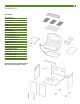
Packing List Description Warming Rack Cooking Grid, 3 pcs. Flavor Activators - 4 large, 3 small Grease Pan Foil Pan Left Side Shelf with Side Burner Side Burner Control Knob Hood/Body Right Side Shelf Bottom Body Panel Front Crossbar Cabinet Side Panel- Left Back Panel Brace wire Cylinder Retainer Bolt Cabinet Upright Cabinet Back Panel Cylinder Blocking Wire Cabinet Side Panel- Right Cabinet Bottom Panel Locking Caster, 2 pcs. Fixed Casters, 2 pcs.
Contents Packing Lists ................................................................ 3 Preparation for Assembly .......................................... 4 Assembly Instructions Step 1 Caster Assembly ......................................... 5 Step 2 Cabinet Bottom Assembly ........................... 5 Step 3 Side Panel Assembly ................................... 6 Step 4 Front Crossbar Assembly............................. 7 Step 5 Cabinet Upright Assembly...........................
Assembly Instructions Step 1 Caster Assembly Lay Cabinet Bottom Panel upside down, so that the flat surface is on the floor. Assemble Fixed Casters to the LEFT Side (the side closest to the cutouts) of Cabinet Bottom Panel and Swivel Lock Casters to the RIGHT Side of Cabinet Bottom Panel. Insert 1/4-20 x .60” Bolts through the caster bracket holes into the threaded holes in the Cabinet Bottom Panel. Tighten the bolts. Push the lever on the two Locking Casters to lock so the caster wheels do not roll.
Step 3 Side Panel Assembly Attach Left Side Panel and Right Side Panel to Cabinet Bottom Panel with six 1/4-20 x .50” Bolts and 1/4-20 Nuts. 1/4-20 x .50” Bolt set 6 pc Secure Left and Right Side Panels to Back Panel with four 5/32 x .31” Bolts through the inside of the Back Panel. 5/32 x .
Step 4 Front Crossbar Assembly Turn cart assembly up on casters. Attach Front Crossbar, with the triangle braces facing down and the flat surface to the front, to Side Panels with six 1/4-20 x .50” Bolts into the threaded holes in the top inside ends of Side Panels. front crossbar 1/4-20 x .50” Bolt set 6 pc Step 5 Cabinet Upright Assembly Attach Cabinet Upright to Cabinet Bottom and Front Crossbar with four 5/32 x .31” Bolts.
! WARNING To reduce the risk of serious bodily injury or death from fire or explosion: • Never remove guards or devices to prevent storage of spare or oversize LP Gas Cylinders not recommended for this grill. Step 6 A. Cylinder Guard Assembly Attach Wire Guard to Front Crossbar and Back Panel with two 5/32 x .47” Bolts. B. Cylinder Blocking Wire Assembly Attach Cylinder Blocking Wire to Right Side Panel with one 5/32 x .47” Bolt and nut. Attach to Bottom Panel with one 5/32 x .47” Bolt.
Step 8 Door Assembly Install LEFT Door. Drop bottom door pin into Cabinet Bottom Panel hole. Swing top of door toward hole in top of Left Side Panel. Depress spring-loaded pin with thumb while sliding pin into Left Side Panel hole until it snaps into place. Assemble RIGHT Door in the same way. Depress Left Door shown, Right Door same. ! CAUTION To reduce the risk of bodily injury from lifting, the following assembly steps #s 9 and 10 will require two people.
! CAUTION Prior to performing any further assembly, PERFORM “FIRST TIME USE” LEAK TEST as detailed on pages 17-18. If the grill is fully assembled before performing the First Time Use leak test, the side tables will need to be removed in order to perform the leak test on the main burner valves inside the control panel, behind the knobs, . Step 10 Side Table Assembly A. Screw two 1/4-20 x .50” Bolts into the two bottom threaded inserts on the outside of the Bowl. Do not screw Bolts all the way.
CAUTION To avoid possible damage to grill, DO NOT ATTEMPT TO LIFT GRILL BY THE SIDE TABLES Step 11 Side Burner Valve Assembly NOTE: Side Burner Valve is already attached to the regulator hose. A. Install the Side Burner Valve from underneath the LEFT Side Table. First insert the valve stem out through the hole in the bezel and fascia on the front of the side table. Next, flex the tube of the burner down and insert the nozzle into the opening in the burner tube. B. Install two 5/32” x .
! CAUTION To avoid possible damage to grill, DO NOT ATTEMPT TO LIFT GRILL BY THE SIDE TABLES Step 13 A. Side Burner Control Knob Assembly Align the flat keyed hole in the Control Knob with the keyed stem of the Side Burner Valve. Push the Control Knob onto the Side Burner Valve stem. B. Side Burner Grid Assembly Place the Side Burner Grid onto Side Burner Table, allowing the three protruded ends to fall into the three holes around the Side Burner. A B Step 14 A.
! CAUTION To reduce the risk of a laceration hazard: • Wear protective gloves when installing warming rack. Hood and Bowl edges could be sharp. Step 15 Warming Rack / Flavor Activator / Cooking Grid Assembly A. Insert Warming Rack leg ends into holes on top edge of firebox. Seat securely. B. Lay a large Flavor Activator over each Burner on the lower body ridges. Lay a small Flavor Activator between each large Flavor Activator.
Connecting/Disconnecting the Gas Using Gas ! DANGE R Carbon Monoxide Hazard • This appliance can produce carbon monoxide which has no odor. Using it in an enclosed space can kill you. • Never use this appliance indoors, on recreational vehicles, or boats. ! WARNING To reduce the risk of serious bodily injury or death from fire or explosion: • Use only propane gas with this LP gas grill. • Do not attempt to convert an LP unit to natural gas.
LP Hose and Regulator ! WARNING To reduce the risk of serious bodily injury or death from fire or explosion: • Clean and inspect the gas hose/regulator before each use of the outdoor cooking gas appliance. The gas hose/regulator must be replaced prior to being used, if there is evidence of excessive abrasion or wear, or if the hose is cut or leaks. • Use only the gas hose/regulator assembly that has been supplied with this gas grill. Do not use hose/regulator from another manufacturer.
Before Using Your LP Gas Grill Installation Codes ! WARNING To reduce the risk of serious bodily injury or death from fire or explosion: • This installation must conform with local codes or, in the absence of local codes, with either the National Fuel Gas Code, ANSI Z223.1/NFPA 54 Natural Gas and Propane Installation Code, CSA B149.1, or Propane Storage and Handling Code, B149.2 or the Standard for Recreational Vehicles, ANSI A 119.
How to Perform A Leak Test “FIRST TIME USE” and as required Supplies Needed for a Leak Test: • Clean paint brush • Water • Dish washing liquid 1. Use an LP Gas Cylinder equipped with an OPD (Overfill Prevention Device) and have it filled at an authorized LP gas dealer by a qualified attendant. 2. Make sure all grill Control Panel Knobs are turned to the “Off” position and verify that the LP Gas Cylinder valve is closed by turning the knob on the LP Gas Cylinder clockwise until it stops. 3.
6. Check for leaks by brushing the soap solution on all gas valves, hose connections and fittings. (Shown by the heavy arrows in Fig. 3a, 4 and 5) Make sure you generously brush the locations with the soap solution, completely surrounding the connections and fittings. Fig. 4 Fig. 4a NOTE: After checking the connections and fittings in Figure 4, replace the control panel in the same manner as it was removed.
Lighting the Grill Using the Pulse-Spark Ignitor ! WARNING To reduce the risk of death or serious injury from an explosion or a fire beneath the grill: • Inspect and clean Burner/Venturi Tubes for insects or insect nests. Spiders or small insects can build nests, webs, and lay eggs in the grill’s Venturi Tubes, (Fig 15, page 28) obstructing the flow of gas to the Burner.
5. Push the Igniter Button in until the Burner is lit. Listen for the spark ignition, and look to make sure the Burner is lit. If no spark, see Troubleshooting Section on page 31. 3/16” gap Gas Collector Box - If no spark, pinch together or open Gas Collector Box to adjust 3/16” gap between electrode tip and V-notch. Fig. 10 6. From the “Off” position, light all other Burners from left to right, making sure each Burner is lit before lighting the next.
Manually Lighting the Grill ! WARNING To reduce the risk of serious bodily injury or death from fire or explosion: • Open Hood before lighting the grill to prevent an explosion from gas build-up. 1. Open the Hood. 2. IMPORTANT: Make sure Control Knobs are turned “Off.” (Fig. 7, P.19) 3. Turn the LP Gas Cylinder valve open counterclockwise until it stops. (Fig. 8, P.19) 4. Locate either the left or right match-lighting hole you intend to use underneath the Grill Bowl.
Lighting the Side Burner ! WARNING To reduce the risk of serious bodily injury or death from fire or explosion: • Open Side Burner Lid before lighting the grill to prevent an explosion from gas build-up. 1. Open the Side Burner Lid. (Fig. 13) NOTE: Side Burner Lid is to remain open while the Side Burner is on or hot. 2. IMPORTANT: Make sure the Side Burner Control Knob is turned “Off” first. (Fig. 7, P.19) 3. Turn the LP Gas Cylinder valve open counterclockwise until it stops. (Fig. 8, P.19) 4.
Manually Lighting the Side Burner ! WARNING To reduce the risk of serious bodily injury or death from fire, explosion or burn hazard: • Open Side Burner Lid before lighting the grill to prevent an explosion from gas build-up. • When manually lighting Side Burner, use Matchlight Holder. 1. Open the Side Burner Lid. 2. IMPORTANT: Make sure Side Burner Control Knob is turned “Off” first. 3. Turn the LP Gas Cylinder valve open counterclockwise until it stops. (Fig. 8, page 19) 4.
Cooking On the Gas Grill ! WARNING To reduce the risk of serious bodily injury or death from fire, explosion or burn hazard: • Never use charcoal or lighter fluid in your gas grill. Keep this outdoor cooking appliance clear and free from combustible materials, gasoline, and other flammable vapors and liquids. • Keep any electrical supply cord and regulator hose away from any heated surfaces.
Grill Cooking (Direct Method) Direct Cooking on the Grids: Food is cooked directly over the heat source. The Burners heat up the Flavor Activators under the Cooking Grids, which in turn heat the food on the grill. The natural food juices from cooking fall onto the hot Flavor Activators below and vaporize. Rising smoke bastes the food, giving it that unique barbecued flavor. Use the Direct Cooking method for foods that take less than 25 minutes to cook: steaks, chops, kabobs, sausages, and more.
Warming Rack ! WARNING To reduce the risk of fire or flare-up from grease drippings: • When cooking food on the warming rack, make sure no Burners are on directly under the Drip Pan. • Clean grease drippings away from grill after each use. Warming Racks are a convenient way to cook food, keep cooked food warm or to warm items such as bread or rolls. To keep foods warm, set the Burners on Low or turn off all that are not needed.
Care and Maintenance ! CAUTION To reduce the risk of a laceration hazard, wear protective gloves when handling parts that have sharp edges. Cleaning the Grill Bottom Panel, Grease Pan, Foil Pan: Remove the two bolts on the sides securing the Bottom Panel. (Step 14, page 12) Scrape away food and fat residue from the Bottom Panel. Empty and wash the Foil Pan and Grease Pan with hot soapy water and a cloth. The Foil Pan can be replaced with a standard size foil pan. (approx.
In order to prevent flashbacks, the Burner(s) should be removed from the grill and cleaned periodically, especially if the grill has been stored for an extended period of time. Valve Control Knob Burner Spide webs or nest inside Venturi Tube Fig. 15 Venturi Tube How to Clean the Burners 1. Make sure the Control Knobs are turned “Off” and the grill is completely cooled. 2. Carefully remove Cooking Grids and Flavor Activators. 3.
5. Use a pipe cleaner to clear insect nests from the inlet hole of Main Burner (Fig. 19) and Side Burner tube. (Fig. 20) 6. Open up the Main Burner holes (Fig. 19) and the Side Burner holes (Fig. 21) with a small nail or wire. Use a nonmetallic brush to remove food particles and corrosion from the Burner surfaces. Open up Main Burner holes with a small nail or wire. Non-metallic Wire Brush Fig. 20 Fig.
Storage ! WARNING To reduce the risk of serious bodily injury or death: • Store your LP gas grill in a cool dry place. Do not store an LP Gas Cylinder in a space greater than 125 degrees Fahrenheit. Never store a connected LP Gas Cylinder in a building, garage, or any enclosed area. • Store LP Gas Cylinders outdoors out of reach of children. • Never store an LP Gas Cylinder indoors (empty or filled) unless it is disconnected from the gas grill and the cylinder’s Gas Supply is turned “OFF.
Emergencies Problem Possible Cause Solution Gas leaking from cracked/cut/burned hose Damaged hose Turn off gas at the LP Gas Cylinder. Replace valve/hose regulator before continuing use. Gas leaking from LP Gas Cylinder Mechanical failure due to rust or mishandling Replace LP Gas Cylinder. Gas leaking from LP Gas Cylinder valve Failure of valve from mishandling or mechanical malfunction Turn off LP Gas Cylinder valve. Return Cylinder to gas supplier.
Troubleshooting Problem Possible Cause Solution Regulator coupling nut is not fully connected to LP cylinder Tighten coupling nut by hand about one-half to three quarters additional turn. Do not use tools. LP-Excess flow valve tripped in regulator Turn Control Knobs to “Off” position and turn LP Gas Cylinder handle clockwise until it stops. Wait five minutes. Relight LP gas grill. If flame continues to be low, turn off gas at LP Gas Cylinder and grill.
Problem Possible Cause Solution Flare up Grease build-up Clean grill. Excessive fat in meat Trim fat from meat before grilling. Persistent grease fire Grease trapped around burner Turn Control Knobs “Off” and turn handle of LP Gas Cylinder system clockwise until it stops. Open Hood carefully and let fire burn out. After the grill cools, remove and clean all parts.
Parts Illustration 19 If you need replacement parts, refer to the Parts Illustrations to find the exact parts you need. If you have any questions or need help, contact Customer Service at 1-800-251-7558 or go to www.aussiegrills.com. Be sure to have the grill model number and serial number printed on the black label, located inside the left door of the cabinet. If you need a replacement part under warranty, a proof of purchase will be necessary.
Parts List Key 1 2 3 4 5 6 7 8 9 10 11 12 13 14 15 16 17 18 19 20 21 22 23 24 25 25A 26 27 28 29 30 31 32 33 34 35 36 37 38 39 40 41 42 43 44 45 46 47 48 49 Description Side Burner Cover Side Burner Cooking Grid Left Side Table Side Burner Valve Side Burner Knob Bezel Control Knob Side Burner Ignition Box Main Knob Bezel Front Crossbar Cylinder Wire guard Cabinet Side Panel- LEFT Cabinet Upright Cylinder Retainer Bolt Cabinet Bottom Panel Cabinet Door- LEFT Cabinet Door- RIGHT Handle, Door Hood Handle
Limited Warranty MECO CORPORATION - LIMITED WARRANTY This product is warranted to the original consumer purchaser against defects in material and workmanship under normal outdoor household use and correct assembly (if assembled by the consumer purchaser). Burners are warranted for a period of two (2) years from the date of purchase. Stainless steel parts are warranted for a period of one (1) year (for rust-through only) from the date of purchase.