LTC 8770 Series Instruction Manual EN Relay Units
LTC 8770 Series | Instruction Manual | Important Safeguards EN | 2 Important Safeguards 1. Read, Follow, and Retain Instructions - All safety and operating instructions should be read and followed before operating the unit. Retain instructions for future reference. 2. Heed Warnings - Adhere to all warnings on the unit and in the operating instructions. 3. Attachments - Attachments not recommended by the product manufacturer should not be used, as they may cause hazards. 4.
EN | 3 LTC 8770 Series | Instruction Manual | Safety Precautions For Indoor Product 1. Water and Moisture - Do not use this unit near water - for example, in a wet basement, in an unprotected outdoor installation or in any area classified as a wet location. 2. Object and Liquid Entry - Never push objects of any kind into this unit through openings, as they may touch dangerous voltage points or short out parts that could result in a fire or electrical shock. Never spill liquid of any kind on the unit. 3.
EN | 4 LTC 8770 Series | Instruction Manual | FCC & ICES Information FCC & ICES INFORMATION Sicherheitshinweise (U.S.A. and Canadian Models Only) This device complies with part 15 of the FCC Rules. Operation is subject to the following two conditions: (1) This device may not cause harmful interference, and (2) This device must accept any interference received, including interference that may cause undesired operation.
EN | 5 LTC 8770 Series | Instruction Manual | Safety Precautions Veiligheidsmaatregelen VOORZICHTIG: OPEN DE BEHUIZING OF DE ACHTERKANT VAN HET APPARAAT NIET. ZO VERMINDERT U HET RISICO OP ELEKTRISCHE SCHOKKEN. IN HET APPARAAT BEVINDEN ZICH GEEN ONDERDELEN DIE U ZELF KUNT REPAREREN. LAAT SERVICE EN ONDERHOUD UITVOEREN DOOR GEKWALIFICEERD PERSONEEL. Medidas de Segurança CUIDADO: PARA REDUZIR O RISCO DE CHOQUE ELÉCTRICO, NÃO RETIRE A TAMPA (OU A PARTE POSTERIOR).
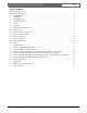
LTC 8770 Series | Instruction Manual | Table of Contents EN | 6 Table of Contents Important Safeguards . . . . . . . . . . . . . . . . . . . . . . . . . . . . . . . . . . . . . . . . . . . . . . . . . . . . . . . . . . . . . . . . . .2 FCC & ICES Information . . . . . . . . . . . . . . . . . . . . . . . . . . . . . . . . . . . . . . . . . . . . . . . . . . . . . . . . . . . . . .4 1 UNPACKING . . . . . . . . . . . . . . . . . . . . . . . . . . . . . . . . . . . . . . . . . . . . . . . . . . . . . . . . .
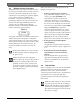
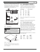
EN | 7 LTC 8770 Series | Instruction Manual | Unpacking 1 UNPACKING 3 Unpack carefully. This electronic equipment should be handled with care. Check for the following items: • Verify the Relay Unit model number, LTC 8770/60 or LTC 8770/50 • Four 12-pin relay screw terminal connectors • One 3-pin biphase screw terminal connector If the item appears to have been damaged in shipment, replace it properly in its carton and notify the shipper.
EN | 8 LTC 8770 Series | Instruction Manual | Installation 4.3 Biphase Control Code Input The biphase control code input connection is made to the 3-pin screw terminal connector located on the rear of the unit. This is the communications port where commands are received using the proprietary biphase protocol. The CODE_IN +, SHIELD, and CODE_IN – wires are connected to the device generating the biphase code (such as the output from an LTC 8568 Series Signal Distribution unit).
EN | 9 LTC 8770 Series | Instruction Manual | Installation Remove the cover following the directions below, later paragraphs describe in detail each DIP switch function. Locate all DIP switch positions on the circuit board using FIGURE 1. Set the DIP switches to obtain the desired operation, then re-install the cover. 4.5 Selecting Modes of Operation Switches S105-1 through S105-3 determine the mode of operation for the unit. There are seven modes of operation.
EN | 10 LTC 8770 Series | Instruction Manual | Installation 4.7 Monitor Number Thumb-wheel switches S101, S102, S103, and S104 collectively make up and determine the monitor number selection. The number dialed on these switches indicates the monitor number to respond to when commands are sent with monitor information. The monitor number is read once on power-up and the value of the number is read conventionally.
EN | 11 LTC 8770 Series | Instruction Manual | Operation 5 OPERATION Once the application has been determined, the operational setup of the LTC 8770 must be implemented via DIP switches. BEFORE connecting power to the unit, the internal DIP switches should be set for the desired operation. The DIP switches are read by the unit on power-up and should be only changed when the system is unplugged and the power is OFF. The Relay Unit has two main operating modes, and several sub-modes.
EN | 12 LTC 8770 Series | Instruction Manual | Operation It is also possible to control the relays of a LTC 8770 unit when it is connected to an Allegiant Series matrix switcher, by using Allegiant Command Console Language (CCL) commands. Refer to the Allegiant CCL Manual (available for download from www.boschsecuritysystems.com) for complete details on controlling an Allegiant switcher using ASCIIbased commands from an external device.
EN | 13 LTC 8770 Series | Instruction Manual | Operation This mode responds only to cameras in an alarm condition (alarm cameras). The physical relay whose Logical Relay Number corresponds to the alarm camera being displayed on this selected monitor will activate indefinitely. If the monitor displays a camera not in an alarm condition (non-alarm camera), no relay is activated. This mode is basically identical to Mode 3, except that it only responds to Cameras in Alarm.
EN | 14 LTC 8770 Series | Instruction Manual | Pin Outs 6 PIN OUTS 6.1 Biphase Code in Connector Relay Contacts OUT Biphase IN Pin 1 2 3 Connection Code In + Shield Code In - Allegiant LTC 8770 Figure 5 Configuration Example 6.
LTC 8770 Series | Instruction Manual | Bosch Security Systems | 03 February 2004 EN | 15
Bosch Security Systems, Inc. 850 Greenfield Road Lancaster, PA 17601 USA Tel: 800-326-3270 Fax: 1-717-735-6560 www.boschsecuritysystems.com Bosch Security Systems B.V. P.O. Box 80002 5600 JB Eindhoven The Netherlands Tele +31 40 27 80000 © 2004 Bosch Security Systems GmbH 3935 890 14513 04-06 | February 03, 2004 | Data subject to change without notice. Bosch Security Systems Pte Ltd.