Aussie TM LP Gas Grill Assembly and Use Manual Bonza Deluxe Bonza Kanga ©Aussie™ Grill Company 2001 For Customer Service, call 1-800-251-7558 www.aussiegrill.com This owners manual is intended for the following models: 7462, 7402, 7362, 7302, 7262, 7202 •READ AND FOLLOW INSTRUCTIONS CAREFULLY BEFORE ASSEMBLY OR USE. FAILURE TO FOLLOW THESE INSTRUCTIONS COULD RESULT IN DEATH, SERIOUS BODILY INJURY, AND/OR PROPERTY LOSS. •FOR OUTDOOR HOUSEHOLD USE ONLY. NOT FOR COMMERCIAL USE.
I. IMPORTANT SAFEGUARDS.....................................2 2) Precautions...............................................26 3) Leak Testing..............................................27 C) Operating the LP Gas Grill...........................27 1) Preparation Before Cooking.....................28 2) Lighting Using Integra Spark Ignition.......28 3) Manual Lighting of the Grill......................29 4) Check Your Flame....................................30 4) Grill Cooking.............................
7. WARNING! If your grill catches on fire: • If the fire is in the grill portion and you can safely reach the control knobs, then turn them off by turning knobs clockwise. If you cannot safely reach the control knobs, call the fire department. • If the fire involves one of the hoses, and you can safely reach the propane cylinder valve, shut the valve off by turning LP cylinder valve handle clockwise to a full stop.
30. Use of this LP gas grill other than for the intended use, or alteration of this LP gas grill in any way may not be safe and will void any warranty. 37. Never store an LP gas cylinder indoors (empty or filled). If storing the gas grill indoors, disconnect LP gas cylinder and store it outdoors out of the reach of children. 31. Never attempt to repair the LP gas grill or cylinder yourself. Contact the manufacturer for information regarding repairs to your grill. 38.
ASSEMBLY INSTRUCTIONS for KANGA, BONZA, and BONZA DELUXE MODELS PREPARATION FOR ASSEMBLY: Removing parts from carton and some assembly will require two people. Before starting assembly, read the instructions and your manual. This manual covers several Aussie Grill models. Use only the steps that pertain to your model. Remove all the parts from the carton and lay them on a smooth, clean surface. (You may cut the carton, spread it out, and use it as a pad to protect part finishes.
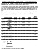
PART/ DESCRIPTION Part# QTY. KANGA BONZA BONZA DELUXE 11 Rear Fixed Leg - Wood *See Bottom Page Note 1 1 Birch Kempas Birch Kempas 12 Front Fixed Leg - Wood *See Bottom Page Note 1 1 Birch Kempas Birch Kempas 13 Rear Fixed Leg - Metal Tubing 03.6091.03 1 Sterling 14 Front Fixed Leg - Metal Tubing 03.6092.03 1 Sterling *See Bottom Page Note 2 2 Birch Kempas Birch Kempas *See Bottom Page Note 1 1 Birch Kempas Birch Kempas 03.5989.00 1 All Models All Models 03.6093.
PART# QTY. KANGA BONZA BONZA DELUXE 03.6094.00 1 All Models All Models All Models 03.5996.00 4 All Models All Models All Models 03.5997.00 03.5998.00 03.5999.00 1 1 1 All Models All Models All Models Grill Body Kanga *See Bottom Page Note 1 1 1 2-Burner 3-Burner 4-Burner Spacer 03.4074.00 8 All Models All Models All Models 03.4066.00 8 All Models All Models All Models 03.6003.
PART/ DESCRIPTION 41 42 43 44 45 46 47 48 BONZA DELUXE PART# QTY. KANGA BONZA 03.6015.00 03.5023.00 03.6016.00 2 2 2 2-Burner 3-Burner 4-Burner 2-Burner 3-Burner 4-Burner 2-Burner 3-Burner 03.6017.00 2 All Models 03.5024.00 1 All Models Bolt, 6mm x 90mm 03.6020.00 2 All Models All Models Hood Handle *See Bottom Page Note 1 1 1 2-Burner 3-Burner 4-Burner 2-Burner 3-Burner 03.6023.00 2 All Models All Models 03.4070.00 2 All Models All Models 03.5033.
STEP 1- WHEEL LEG/ SIDE TABLE ASSEMBLY TOOLS: OR (ITEM 10) ACTUAL SIZE 1/4” X 1 3/8” BOLT 8pcs (ITEM 1, 2, or 4) SIDE TABLE (ITEM 6) FRONT WHEEL LEG - WOOD (ITEM 9) ACTUAL SIZE 1/4” x 1” BOLT 8 pcs (ITEM 8) FRONT WHEEL LEG - METAL TUBING OR (ITEM7) REAR WHEEL LEG - METAL TUBING (ITEM 5) REAR WHEEL LEG - WOOD •Note: There are three side table designs used depending on the model: Square SideTables (Item 1) which can be used on either side, Left and Right Teardrop Side Tables (Item 2 & 3), or Deluxe S
STEP 2- FIXED LEG/SIDE TABLE ASSEMBLY TOOLS: OR (ITEM 1, 3, OR 4) SIDE TABLE (ITEM 9) 8 pcs 1/4” x 1” BOLT (ITEM 10) 8 pcs 1/4” x 1 3/8” BOLT (ITEM 12) FRONT FIXED LEG - WOOD (ITEM 14) FRONT FIXED LEG - METAL OR (ITEM 13) REAR FIXED LEG - METAL (ITEM 11) REAR FIXED LEG - WOOD •In the same way, attach the Front and Rear Fixed Legs to the remaining Side Table using 1/4” x 1” Bolts (1/4” x 1 3/8” for Metal Legs.
STEP 3- LEGBRACE ASSEMBLY Tools: NOTE: Bonza Deluxe Model with metal legs does not use the legbrace. (ITEM 9 ) ACTUAL SIZE 1/4” x 1” BOLT 8 pcs (ITEM 15 ) LEGBRACE 2 pcs •Attach Legbraces onto each Side Table assembly using 1/4” x 1” Bolts. Do not tighten bolts completely.
STEP 4-BOTTOM SHELF/LEG & CASTER ASSEMBLY (ITEM 17 OR 18) AXLE (ITEM 10) 8 pcs 1/4” X 1 3/8” BOLT (DELUXE MODELS) (ITEM 9) 4 pcs 1/4” x 1” BOLT TOOLS: (ITEM 16) BOTTOM SHELF (ITEM 22) 1/4” X 2” BOLT 4 pcs (ITEM 19, 20, 21) CASTER ASSEMBLY •Place Leg/Side Table assemblies opposite each other as shown with the velcro patches on same side. •Place Bottom Shelf inside of Wheel Leg assembly and align large axle holes. Insert Axle through axle holes in both sides of legs and shelf.
STEP 5-WHEEL/ CYLINDER BRACKET ASSEMBLY (ITEM 23, 24, & 25) WHEEL ASSEMBLY 2 PCS TOOLS: (ITEM 27) 4 pcs 1/4” x 1/2” BOLT (ITEM 26) CYLINDER BRACKET •Slide Axle out. With the notched side of Cylinder Bracket down, secure the Cylinder Bracket to wheel end of Bottom Shelf using ¼” x ½” Bolts and tighten. •Slide Axle back into position and push a Wheel Assembly onto each end of axle until the spring clip locks into place. •On Deluxe Models, slide end caps onto each Fixed Leg.
STEP 6-GRILL BODY/CART ASSEMBLY- KANGA MODELS (ITEM 28) BOTTOM BODY PANEL (ITEM 29) GRILL BODY-KANGA (ITEM 31) 6mm x 110mm BOLT 8 pcs ACTUAL SIZE TOOLS: (ITEM 30) Spacer 8 pcs (ITEM 32) 6mm WING NUT 8 pcs CAUTION: Some parts inside the Grill Body may have sharp edges or corners Remove Bottom Body Panel from underneath of Grill Body . •Handle the Grill Body carefully to protect the Body finish. ASSEMBLY CONTINUED NEXT PAGE.
STEP 6-(CONTINUED) ASSEMBLE GRILL BODY TO CART- KANGA MODELS •Turn Grill Body upside down and position between cart legs with the Hose and Regulator on the Wheel Leg end. Do not lay Grill Body on, or step on, the Hose and Regulator. CASTER LOCK 6mm X 110mm BOLT 6mm X 110mm BOLT BODY •Align slotted holes on sides of Grill Body with holes through edges of legs (Fig. E).
STEP 7-GRILL BODY/CART ASSEMBLY- BONZA & BONZA DELUXE MODELS Note: Assembly of Grill Body will require two people. TOOLS: (ITEM 32) 6mm WING NUT 8pcs (ITEM 31 ACTUAL SIZE) 6mm x 110mm BOLT 8 pcs (ITEM 30) SPACER 8 pcs CAUTION: Some parts inside of Grill Body may have sharp edges or corners. (ITEM 33) GRILL BODY-BONZA MODEL Remove Bottom Body Panel from underneath of Grill Body. Handle the Grill carefully to protect the Body and its finish. ASSEMBLY CONTINUED NEXT PAGE.
STEP 7-(CONTINUED) GRILL BODY/CART ASSEMBLY- BONZA MODELS •Lay Grill Body on its back side with control panel up. Place Grill Body between legs and Side Tables with Hose and Regulator on Wheel Leg end. Do not lay Grill Body on, or step on Hose and Regulator. •Align slotted holes on sides of Grill Body with holes through edges of legs (Fig F). Hold Spacers between Leg and Body (Needle Nose Pliers may help) and insert Body Bolts through Leg, Spacers, and slotted holes in Grill Body.
STEP 8-ATTACH DECORATIVE PRIVACY PANEL TO CART - (ALL MODELS) (ITEM 34) DECORATIVE PRIVACY PANEL •Using the 3 Velcro patches found on the inside of each front leg, attach the Privacy Panel with the Aussie logo facing forward. VELCRO PATCHES PRIVACY PANEL ALIGN BOTTOM EDGE OF PANEL TO CURVED EDGE OF BOTTOM SHELF SIDERAIL.
•Fit venturi end of Burner through hole in the inside firewall (behind control panel) and onto Gas Control Valve Nozzle (Fig. G & Fig. H). Be careful not to bend or force gas collector plates. Holes in Front firewall. Manual Lighting Holes Gas Nozzle Control Vavle Gas Collector and Electrode Top plate of gas collector. Venturi end of Burner inserted over gas nozzle. FIG. G FIG. H . REFERENCE: ELECTRODE GAP Adjust Tab if greater than 3/16”. ELECTRODE 3/16” GAP MAX.
STEP 10-INSTALL BOTTOM BODY PANEL/GREASE TRAY- (ALL MODELS) •In upright position and drain hole toward the rear, slide Bottom Body Panel into guides (See Arrows) at bottom of Grill Body. Insert two #8 x 1/2” screws through the holes in guides and Bottom Body Panel; then tighten. Slide Foil Pan and Grease Tray all the way into Bottom Body Panel Brackets.
STEP 12-ATTACH HANDLE TO WEATHER COVER (LID) - KANGA MODELS TOOLS: (ITEM 42) SCREW, #10 X 3/8” 2 pcs (ITEM 43) HANDLE, WEATHER COVER •Insert two #10 x 3/8” Screws through bottom of Weather Cover into Handle and tighten.
STEP 13-ATTACH HANDLE AND HEAT INDICATOR TO HOOD - BONZA MODELS TOOLS: (ITEM 44 ACTUAL SIZE) 6mm x 90mm BOLT 2 pcs (ITEM 46) HANDLE SPACER 2 pcs (ITEM 49) LOCKWASHER 2 pcs (ITEM 45) HOOD HANDLE (ITEM 47) 6mm LOCKNUT 2 pcs (ITEM 50) 10-24 HEX NUT 2 pcs (ITEM 48) HEAT INDICATOR •Insert two 6mm x 90mm Bolts through recessed holes of Hood Handle, through Handle Spacers, into front of hood and secure with 6mm Locknuts. Be sure to place the wide end of Spacer against the Hood.
STEP 14-ATTACH LP CYLINDER TO GRILL - (ALL MODELS) •Fill empty LP Cylinder at your local LP gas supplier. •Set bottom ring of LP Cylinder into Cylinder Bracket through round hole in Bottom Shelf (Fig. K ). Turn Adjusting Knob clockwise to secure LP Cylinder inside Cylinder Bracket(Fig. K). •Turn all control knobs and LP Cylinder valve to the “Off” position. •Take the protective cap off the cylinder valve. (Fig.
STEP 15-LEAK TESTING (TO BE PERFORMED IN A WELL-VENTILATED AREA.) 4) Remove front control panel cover. 5) Open valve on LP gas cylinder (Turn counterclockwise). · Perform a leak test before each use. · Leak test must be performed in a well ventilated area. · Never perform a leak test on a grill while in use or hot. · If you detect a gas leak that cannot be corrected by using the leak test procedures below, do not use the LP gas grill. · Never smoke or have an open flame near the grill during a leak test.
OPERATING AND MAINTAINING YOUR GAS GRILL GAS, CYLINDER, HOSE AND REGULATOR INFORMATION · If you obtain LP gas through a cylinder exchange dealer, make sure you are getting a safe and adequate O.P.D. cylinder. Use only a licensed LP gas cylinder dealer. This LP gas grill was designed to use propane gas. Propane · Keep children away from LP gas cylinder at all times. cylinders will supply gas all year round, even on cold winter days.
Precautions · Never connect or disconnect LP gas cylinder or fittings while grill is in use or is hot. · When the LP gas cylinder is connected, the grill must be kept outside in a well-ventilated space. Turn off all of the grill control knobs and the LP cylinder valve when grill is not in use. · Move gas hose as far away as possible from hot surfaces. · Carefully read the Important Safeguards section of this manual (pages 2 thru 4). Make sure you follow and understand all instructions and warnings.
LeakTesting OPERATING THE LP GAS GRILL · Always perform a leak test before each use. · Leak test must be performed in a well ventilated area. · Never perform a leak test on a grill while in use or hot. · If you detect a gas leak that cannot be corrected by using the leak test procedures below, do not use the LP gas grill. · Never smoke or have an open flame near the grill during a leak test. Supplies Needed for a Leak Test Clean paint brush, water, and dishwashing liquid.
Preparation Before Cooking 3) From the “Off” position, push control knob in on the left burner and turn counter-clockwise until you feel resistance. · Wash the porcelain coated Cooking Grids (41) with a Pause 4 seconds, then continue turning the control knob mixture of hot water and baking soda. until a click is heard and the burner is lit. · Empty the foil pan and grease tray after each cooking 4) Light the remaining burners by turning the control knob session so excessive grease does not accumulate.
Manual Lighting of the Grill 4) Locate the control knob that corresponds to the match lighting hole that you are using. Push in and turn the control knob counter-clockwise until a click is heard. · Open Lid or Hood (depending on the model) before lighting the grill to prevent an explosion from gas build-up. · The Lid (Kanga™ series only) must never be covering the cooking surface while the LP gas grill is in use or hot. · Always inspect the gas hose and regulator assembly before each use.
Check Your Flame End of Cooking Session Your burners have been preset by the manufacturer for optimal flame performance. A blue flame, possibly with a small yellow tip, is the result of the optimal air and LP gas mix· Never leave your LP gas grill unattended during use ture. (See diagram below) or cleaning. After each cooking session, close the hood (Bonza™ series only) and turn the grill burners to the “high” position and burn for five minutes.
Burner Maintenance CARE AND MAINTENANCE (Continued) Regularly clean your LP gas grill between uses and especially after extended periods of storage. Ensure the grill and its components are cool before cleaning. In order to extend the life and maintain the condition of your grill, we strongly recommend that the unit be covered when stored outside for any length of time, especially during the winter months.
Ceramic Briquettes It is not necessary to remove and wash the ceramic briquettes in order to keep them clean. Burning off the residue after each cooking should be sufficient. Heavily impregnated ceramic briquettes should be turned over so that the dirty side faces the burners in order to burn off any residue. Bottom Panel/ Grease Tray · Always turn the LP gas cylinder valve “Off” when not in use. Allow grill to cool before handling parts or cleaning.
TROUBLESHOOTING Problem Burners will not light using the ignitor Burners will not light using a match Low flame or low heat Possible Cause Solution Burners not assembled correctly See Step 9 - Install Burners of the Assembly Instructions Not pausing long enough before clicking the control panel knob When lighting the 1st (Leftmost) Burner, push-in and turn control panel knob counter-clockwise until you feel resistance with turning.
TROUBLESHOOTING Problem Possible Cause Solution Flames blow out High or gusting winds Turn front of grill to face wind or increase flame height. Gas in LP cylinder is low Check LP gas cylinder. Refill if necessary. Excess flow valve tripped See “Low flame” problem above Grease build up Clean grill Excessive fat in meat Trim fat from meat before grilling Persistent grease fire Grease trapped around burner system Turn control knobs “off” and turn handle of LP cylinder clockwise until it stops.
IMPORTANT NOTICE The gas grill is setup to operate with a LP Gas Cylinder equipped with an OPD (Overfilling Prevention Device). This is a secondary device to prevent the overfilling of your LP Gas cylinder. The proper methods for the filling of your LP Gas cylinder are by weight or volume, as described in NFPA 58. Please make sure your filling station fills your LP Gas cylinder by weight or volume.
AUSSIE GRILL COMPANY LIMITED WARRANTY This product is warranted to the original consumer purchaser against defects in material and workmanship under normal outdoor household use and correct assembly (if assembled by the consumer-purchaser). Cast iron burners and porcelain grids are warranted for a period of five (5) years from the date of purchase. All other parts are warranted for a period of one (1) year from the date of purchase.