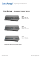
Inspired by Your Data Center User Manual - Automatic Transfer Switch 230V Amp : 10A / 16A Outlet : C13 / C19 208V Amp : 20A Outlet : C13 / C19 110V Amp : 15A / 20A Outlet : US NEMA Designed and manufactured by Austin Hughes UM-IP-ATS-Q215V2 www.austin-hughes.
Legal Information First English printing, October 2002 Information in this document has been carefully checked for accuracy; however, no guarantee is given to the correctness of the contents. The information in this document is subject to change without notice. We are not liable for any injury or loss that results from the use of this equipment. Safety Instructions Please read all of these instructions carefully before you use the device. Save this manual for future reference.
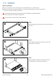
Content Part I. ATS Installation & Connection Page < 1.1 > Package Content 1 < 1.2 > Product Overview 2 < 1.3 > Installation 3 < 1.4 > Power Sources Connection 4 < 1.5 > Devices Connection 4 Part II. Model & Specification < 2.1 > 230V ATS 5 < 2.2 > 208V ATS 7 < 2.3 > 110V ATS 9 Unpacking The equipment comes with the standard parts shown in package content. Check and make sure they are included and in good condition. If anything is missing, or damaged, contact the supplier immediately.
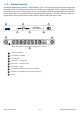
< 1.2 > Product Overview InfraPower Rackmount Auomatic Transfer Switch ( ATS ) with dual power input provides reliable and redundant power for single-corded equipment. By the input preference switch, users can define the preferred power source. If the primary source is unavailable, the ATS will seamlessly source power from the secondary source without power interruption and downtime. The entire ATS series are designed with a local current meter to easily observe power status and device load.
< 1.3 > Installation Before Installation ■ ■ It is very important to mount the equipment in a suitable cabinet or on a stable surface. Make sure the place has a good ventilation, is out of direct sunlight, away from sources of excessive dust, dirt, heat, water, moisture and vibration. All electrical power and power control wiring must be installed by a qualified electrician and comply with local and national regulations.
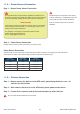
< 1.4 > Power Sources Connection Step 1 : Before Power Source Connection This Transfer Switch requires that the applied AC waveforms from both power sources be in phase with respect to each other. Failure to do so can potentially damage the unit and create an unexpected HIGH VOLTAGE to be present on the pins of either the Primary Source or Secondary Source plug when disconnected, or on the Primary Source or Secondary Source output receptacles.
Part II. Model & Specification < 2.
< 2.
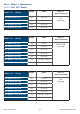
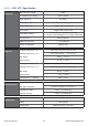
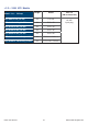
< 2.2 > 208V ATS Models Model List - 20 Amp Height Outlet ATS-H8C13-20A_L6-20P 1U C13 x 8 ATS-H10C13-20A_L6-20P 1U C13 x 10 ATS-H12C13-20A_L6-20P 2U C13 x 12 ATS-H16C13-20A_L6-20P 2U C13 x 16 ATS-H20C13-20A_L6-20P 2U C13 x 20 ATS-H8C13 / 1C19-20A_L6-20P 1U C13 x 8 + C19 x 1 ATS-H16C13 / 2C19-20A_L6-20P 2U C13 x 16 + C19 x 2 UM-IP-ATS-Q215V1 Inlet x 2 ( 3M cord attached ) P.7 L6-20P input plug www.austin-hughes.
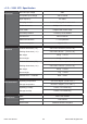
< 2.2 > 208V ATS Specification Nominal input voltage Electrical 208V Acceptable input voltage ±10% nominal Input frequency 50 / 60Hz Inlet plug & cord 2 x L6-20P plug with 3-meter cord Outlet connectors Multiple C13 / C19 outlets Local meter 3-digital LED current meter Overload protection 1 x 20-amp circuit breaker Transfer time Physical 25ms maximum Electrical endurance 1 x 10⁵ operations Power consumption Approx. 8VA Product dimensions ( 1U ) 442 x 270 x 43.
< 2.
< 2.