PDU Inspired by Your Data Center User Manual PPS-02-S, IP dongle GUI software W kWh Monitored PDU WS kWh Switched PDU Wi Outlet kWh Monitored PDU WSi Outlet kWh Switched PDU Designed and manufactured by Austin Hughes UM-PPS-02-S-Q214V1 www.austin-hughes.
Legal Information First English printing, October 2002 Information in this document has been carefully checked for accuracy; however, no guarantee is given to the correctness of the contents. The information in this document is subject to change without notice. We are not liable for any injury or loss that results from the use of this equipment. Safety Instructions Please read all of these instructions carefully before you use the device. Save this manual for future reference.
Unpacking The equipment comes with the standard parts shown on the package contents. Check and make sure they are included and in good condition. If anything is missing, or damage, contact the supplier immediately. Package contents ( 1 ) Vertical W / Wi / WS / WSi PDU x 1 - VMS mounting screw, set of 2 or 3 + - VMB mounting bracket set 2 - 3 sets M4 PEG M4 x 2 Bracket x 2 M6 M6 x 2 M6 nut x 2 M6 nut M4 LINK OUT TH 1 TH 15.9 2 31. 7 15.8 3.49 3.48 6.9 22.3 37.
Content < 1.1 > W / Wi / WSi PDU Key Features P. 1 < 1.2 > IP Dongle GUI Software PPS-02-S Key Features P. 2 < 1.3 > W meter display & setting P. 3 < 1.4 > PDU cascade & connection P. 6 < 1.5 > Temp. / Humidity Sensor Connection & Specification P. 7 < 1.6 > IP dongle installation & connection P. 9 < 1.7 > Easy change on PDU Power Feed Position P. 11 < 1.8 > IP dongle configuration P. 12 < 1.9 > PPS-02-S IP dongle GUI software P. 13 < 1.10 > SNMP Management P. 18 UM-PPS-02-S-Q214V1 www.
< 1.1 > W / Wi / WS / WSi PDU Key Features kWh PDU Outlet kWh PDU Monitored Switched Monitored Switched W WS Wi WSi Outlet Measurement Circuit kWh Measurment Temp-Humid Sensor port x 2 16 Levels in Single Daisy Chain One IP Access 16 PDU Levels SNMP Capability via IP Dongle Hot-pluggable Meter w/ 1.
< 1.2 > IP Dongle GUI Software PPS-02-S Key Features InfraPower Manager PPS-02-S is a FREE built-in GUI software of each IP dongle ( IPD-02-S only ) to remotely monitor the connected PDUs ( max.
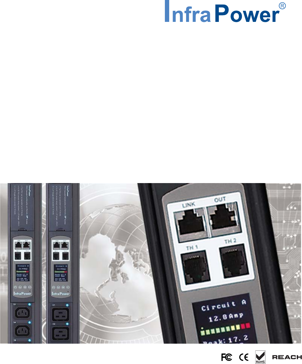
< 1.3 > W meter display & setting All W series PDUs are equipped with a highly advanced and sophisticated component - W Meter. It provides the cascade ports for daisy chain up to 16 x PDU. Furthermore, for IP PDU access, simply connect 1 x IP Dongle for all daisy chain PDUs to save IP network address. Two sensor ports are integrated for temperature & humidity monitoring. Creatively, 1.8” color LCD display offers a real time local monitoring and detailed PDU status. 1 PDU cascade port 2 Temp.
< 1.3 > W meter display W meter 1.8” color LCD provides a sharp and highly visible reading for the local reading of Current ( Amp ), Voltage ( Volt ), Power ( kW ), Energy Consumption ( kWh ), Power Factor, Temperature & Humidity. Display 1.1 Press to change °C / °F Display 6 only for Wi / WSi outlet measurement PDU UM-PPS-02-S-Q214V1 P.4 www.austin-hughes.
< 1.3 > W meter setting W meter allows the user to do some settings below : PDU level setting : Step 1 - Press the & button to display no.9 Step 2 - Press the & button to PDU ID Step 3 - In display 9.1, Press the Step 4 - Press & and press and press to confirm to confirm button to select PDU level no. & press to confirm to exit Buzzer : W meter allows the user to set the meter buzzer ON / OFF by meter’s 4 buttons Screen OFF : All PDUs are shipped with the metter LCD in always ON status.
< 1.4 > PDU cascade & connection PDU Daisy Chain up to 16 Levels The W meter built-in not only provides the local power monitoring, but also the connection ports for the PDU daisy chain. For daisy chain connection, each PDU just simply to be connected in series to the next by Cat5/6 cables. Maximum 16 PDUs are supported in one daisy chain group.
< 1.5 > Temp. & Humidity Sensor Connection & Specification W meter provides 2 sensor ports for Temp. & Humidity monitoring. The user can see the Temp. / Humidity reading not only from the local meter display but also from remote management software. • • • • low profile design with magnetic base for easy affixing to the rack cabinet Plug n Play sensor with 2M or 4M cord pair of sensors can be connected to a single W meter Temp. & Humid.
< 1.5 > Temp. & Humidity Sensor Connection & Specification Part no. Temperature Sensitivity Temp. & Humid. Sensor Temp. Sensor IG - TH01 IG - T01 Range Accuracy 0 to 80°C ( 32 to 176°F ) Resolution 0.1°C ( 0.2°F ) Response Time Relative Humidity Sensitivity Range Accuracy Resolution Response Time Power Requirement 5 to 30 sec 0 to 100% R.H / 0 to 100, ±8.0% R.H 20 to 80, ±4.5% R.H. / 1% R.H.
< 1.6 > IP dongle installation & connection IP Dongle Access to 16 PDU Levels Patented IP Dongle provides IP remote access to the PDUs by a true network IP address chain. Only 1 x IP dongle allows access to max. 16 PDUs in daisy chain - which is a highly efficient application for saving not only the IP remote accessories cost, but also the true IP addresses required on the PDU management. Hot-Pluggable design facilitates the IP dongle installation.
< 1.6 > IP dongle installation & connection IP dongle for rackmount PDU Model : IPD-H02-S ( with SNMP feature ) IP dongle Horizontal IP dongle installation steps : - fix the IP dongle on the rear side of rackmount PDU with 4 screws - plug the RJ-45 connector of IP dongle into the LINK port of the 1st level PDU meter - use the CAT.
< 1.7 > Easy Change on PDU Power Feed Position Power Feed Entry Flexibility - By Meter Setting Customization of top feed power entry is available on request. The change of the power feed entry position is possible after installation. The W series meter provides the flexibility to simply turnover on top feed PDUs with the use of meter inversion buttons and an alternative membrane.
< 1.8 > IP dongle configuration After the completion of IP dongle connection, please take the following steps to configure the IP dongle : Step 1. Prepare a notebook computer to download the IP setup utilities from the link : http://www.austin-hughes.com/support/utilities/infrapower/IPdongleSetup.msi Step 2. Double Click the IPDongleSetup.msi and follow the instruction to complete the installation Step 3. Go to each first level PDU with the notebook computer & a piece of CAT.
< 1.9 > PPS-02-S IP dongle GUI software Each IP dongle ( IPD-02-S ) provides a FREE built-in GUI software, PPS-02-S, which allows user, via an I.E. web browser, to see PDU’s data and remotely manage the PDU over a TCP / IP Ethernet network. Each I.E. supports only one IP dongle ( IPD-02-S ). If user installs more IP dongles, multi windows will be required PPS-02-S is a management software with very limited features. User can use more advanced software, InfraPower Manager IPM-03 Step 1.
< 1.9 > PPS-02-S IP dongle GUI software In < Details >, - Change “ Name ” and “ Location ” of PDU & Click “ Apply ” Change “ Alarm amp. ” & “ Low alert amp. ” of PDU’s circuits & Click “ Apply ” Click “ Reset ” to reset peak amp.
< 1.9 > PPS-02-S IP dongle GUI software In < TH status >, - View status, location, lastest reading & alarm setting of Temp. & Humid sensors connected to each PDU In < TH setting >, - “ Activate ” or “ Deactivate ” Temp. & Humid sensors - Change “ Location ” & “Alarm Setting ” of Temp. & Humid sensors - Click “ Apply ” to finish the above settings UM-PPS-02-S-Q214V1 P.15 www.austin-hughes.
< 1.9 > PPS-02-S IP dongle GUI software In < System >, - Change IP dongle name & location Change temperature unit displayed in UI Change IP dongle’s IP address, subnet mask & gateway Tick “ Force HTTPS ” to provide data transmission security. Click “ Apply ” to finish the above settings In < Login >, - Change “ Login name ” OR “ Password ” - Re-enter password in “ Confirm password ” - Click “ Apply ” to finish the above settings UM-PPS-02-S-Q214V1 P.16 www.austin-hughes.
< 1.9 > PPS-02-S IP dongle GUI software In < Firmware >, you can upgrade the IP dongle firmware. Step 1. Download the IP dongle firmware from the link : http://www.austin-hughes.com/support/software/infrapower/V2395S.img Step 2. Click “ Browse ” and select the firmware file ( xxx.img ) from the specific path in the pop up window and Click “ Open ” Step 3. Click “ Upgrade ” to start the upgrade process. It takes a few minutes to complete. Step 4. Once complete, UI will return to the login page.
< 1.10 > SNMP Management The IP dongle can manage the connected W series PDUs in a single daisy-chain up to 16 PDUs via SNMP v2c ( Simple Network Management Protocol). Only IP dongle model : IPD-02-S or IPD-H02-S can support SNMP ( I ). Accessing MIB Files Use the World Wide Web (WWW) to download the SNMP MIB file at this URL: http://www.austin-hughes.com/support/utilities/infrapower/IPD-MIB.mib ( II ).
< 1.10 > SNMP Management Step 5. Select the SNMP from the left navigation Step 6. The SNMP Settings window appears as below: Step 7. Click “ Enable “ in “ SNMP Agent “ to start the SNMP agent service Step 8. Input “ Read Community “. Default is “ public ” Step 9. Input “ Write Community “. Default is “ private ” Step 10. Select “ disabled “ or “ V2Trap “ in “ SNMP Traps “ If select “ V2Trap “ , please input IP address of the SNMP management station in “ Station IP: “ Step 11.
The company reserves the right to modify product specifications without prior notice and assumes no responsibility for any error which may appear in this publication. All brand names, logo and registered trademarks are properties of their respective owners. Copyright 2014 Austin Hughes Electronics Ltd. All rights reserved. UM-PPS-02-S-Q214V1 www.austin-hughes.