AUSTIN MODELS 1140 SERIES GS4 GD3 GDS DECEMBER THE AUSTIN MOTOR Publication No.
ii AUSTIN A40 SERVICE MANUAL This manual has been compiled to assist Austin Distributors and Dealer Organisations in the efficient servicing and maintenance of the A40 Models. Each assembly of the major components is described in detail. In addition, comprehensive instructions are given for complete dismantling, assembling, adjusting and inspection of these assemblies. It is emphasized that only genuine Austin parts should be used as replacements for components found unfit for further service.
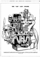
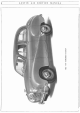
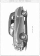
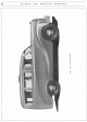
AUSTIN A 40 THE "A40" SERVICE MANUAL O.H.V. ENGINE A sectional view of the engine showing the detail of the main components. Although the A40 "Sports" manifolds and carburetters differ to those of the above illustration the main construction and servicing operations are identical unless otherwise stated.
iv AUSTIN A40 SERVICE MANUAL
AUSTIN A40 SERVICE MANUAL v Cll f- ~ 0 c..
vi AUSTIN A40 SERVICE MANUAL 'IJ.i c..
AUSTIN A40 SERVICE MANUAL vii z ~ u 0
viii AUSTIN A40 SERVICE MANUAL UJ ::c 1-
AUSTIN A40 SERVICE MANUAL ix
AUSTIN A40 SERVICE xi MANUAL GENERAL INDEX Axle (Rear) Bodywork Brakes Clutch Cooling System Electrical Equipment Engine Frame Front Hubs and Independent Front Suspension Fuel System Gearbox ... General Specification ... Regular Attentions Section " " " " ... " " " " Page ... xiv ... xvii INSTRUMENTS AND CONTROLS Section Driving ... Foot Controls .. . Hand Controls .. .
xii AUSTIN Examination for Wear . .. Bearings Clutch Shaft Bushes First and Third Motion Shaft Bush .. . Gear Synchronising Cones Laygear Thrust Washers Layshaft and Bushes Third Motion Shaft Sleeve Gear Change l\1echanism Adjustment Description Lubrication Page 7 7 7 7 7 7 7 7 11 11 II 12 A40 MANUAL SERVICE Page 1 1 1 1 Hubs Reassembly Removal Replacement REAR SUSPENSION Springs ... Data Description Dismantling Replacement Removal .. Shackle Bush Renewal Shackle Removal Section L 2 1 1 2 2 I 2 ...
AUSTIN Page Removing and Refitting the Body (Saloon and Coupe) ... Removing and Refitting the Body (Commercials) Removing and Refitting the Body (Sports) 11 16 25 A40 SERVICE MANUAL Page SERVICE TOOLS Section Q Engine and Clutch Tools I Front Suspension and Hub Tools 3 Gearbox Tools 3 Oil Gun ...
xiv AUSTIN A40 GENERAL SERVICE MANUAL SPECIFICATIONS THIS manual contains information for vehicles of chassis number 657001 and engine number 700001 onwards, Some models prior to this were fitted with series G.S.3. engine (see manual publication No. 441D). When ordering parts note engine and chassis numbers quoted on spare parts list. The engine number is located on the right-hand side of the cylinder block and the chassis number on the chassis.
GENERAL SPECIFICATION XV LEADING DIMENSIONS English A40 SALOON DIMENSIONS ft. ins. Pedal to Seat Squab ... ... Steering Wheel to Seat Squab ... ... ... { 23 105 1 5 10 1 2 7 1 7t 2 10! 3 11 3 ot 3 7 1 6! A B { ...... ...... ...... ...... ... ... ......... ... ...... ......... Distance between Seats c Rear Seat Cushion Depth" D Height over Rear Seat ... E Maximum Interior Height F Height over Front Seat ...
xvi GENERAL A40 VAN DIMENSIONS English Pedal to Seat Squab .. . . .. . .. A Steering Wheel to Seat Squab ... B Steering Wheel to Seat .. . . .. c Height of Seat above Floor ... D E Seat Cushion Depth .. . . .. Height over Seat .. . . .. . .. F Cab Floor to Ground (unladen) ... G Length of Body Floor .. . . .. H Body Interior Height .. . . .. I J Height of Rear Door Opening ... Overall Height (unladen) . .. . .. K Body Floor to Ground (unladen) .. . L Centre of Front Wheel to Bumper .. . M Wheelbase ...
AUSTIN A40 SERVICE MANUAL xvii REGULAR ATTENTIONS The following is a convenient list of regular attentions which the car should receive to keep it in good mechanical condition. These instructions should be closely followed, whether the attentions are performed by the owner or the local garage.
xviii REGULAR ATTENTIONS EVERY 2,000 MILES (3,200 l{m.) Engine Drain the sump and refill with new oil. Capacity is 7 pints, inclusive of filter. Gearbox Check the level and top up if necessary. For access lift the front carpet and remove the small plate on the side of the gearbox covering. The filler plug is then accessible. Clean any dirt or grit away from around the plug. Remove the plug and fill up to the bottom of the threads. This gives the correct level.
REGULAR Distributor Cam Apply a trace of engine oil to the distributor cam. Do not let any oil reach the contact breaker points. ATTENTIONS xix Distributor Automatic Advance Remove the distributor cap and add a few drops of engine oil through the hole in the contact breaker base through which the cam passes. EVERY 5,000 MILES (8,000 l{m.) Gearbox Drain when the oil is warm, after a run, and refill to the level of the filler plug with new oil. Capacity, 3 pints.
XX REGULAR ATTENTIONS EVERY 10,000 MILES (16,000 l{m.) Universal Joints Lubricate the universal joints. The front joint is best lubricated from above, through the hole in the propeller shaft tunnel, at a point between the two front seats. The rear joint must be lubricated from below. Move the car to bring the nipples to the required positions. Also test the flange bolts and tighten if these have worked loose ; the nuts are secured with tab washers.
REGULAR EVERY 5,000 MILES (8,000 Km.) Decarbonising, Valve Grinding and Tappet Adjustment This attention may not be needed so frequently on cars used for long journeys. As a general rule, a falling off in engine power with pinking indicates when decarbonising is due. This operation entails such preliminary dismantling of components as the carburetter, manifolds, cylinder bead and push rods. The correct valve clearance, measured between the rocker arm and the valve stem, is . 015in.
SECTION A INSTRUMENTS & CONTROLS SERVICE JOURNAL REFERENCE NUMBER I DATE I SUBJECT CHANGES -' 1- I ·- I
AUSTIN A40 SERVICE MANUAL A/1 INSTRUMENTS AND CONTROLS Fig. 1. Driving Controls (Saloon and Coupe). A. Demisting vents. B. Trafficator switch. C. Horn Button. D. Gear lever. E. Handbrake. F. Accelerator pedal. G. Brake pedal. H. Clutch pedal. J. Dip switch. INSTRUMENTS Speedometer Registers the vehicle speed and the total mileage.
A/2 INSTRUMENTS Fig. 2. Fig. 3. AND CONTROLS Fascia panel (Saloon) Fascia panel (Commercials) Fig. 4.
INSTRUMENTS AND CONTROLS A/3 Caption for Fig. 2. A. Fuel gauge. B. Ammeter. c. Headlight beam warning light D. Speedometer. E. Ignition warning light. F. Oil pressure gauge. G. Water temperature gauge. H. Choke control. J. Windscreen wiper control. K. Extra air control. L. Air control. M Demisterjdefroster control. N. Ignition and lighting switch. o. Heater motor switch. A. Choke control. B. Windscreen wiper switch. c. Ignition and lighting switch. D. Speedometer. E. F. G. H. P.
INSTRUMENTS A/4 AND CONTROLS Starter Control Knob Pull out the knob to start and release as soon as the engine fires. If the engine fails to start after a few revolutions, do not operate the starter again until the engine is stationary. Heater Controls (Saloon and Coupe) These are situated centrally below the fascia and provide the means for regulating the heating and demisting system. Full operating instructions are given on page P/10.
INSTRUMENTS Spare Wheel For the Saloon, Coupe and Sports the spare wheel is housed in the luggage boot. The Commercials have a separate compartment under the floor boards accessible through a panel at the rear of the vehicle. Front Seats The close fitting front seats are adjustable, with ample backward and forward movement when the spring-loaded trigger (in front of the seat) is operated. Doors The right-hand side front door of all models in the A40 range are locked with the ignition key.
A/6 INSTRUMENTS for manual tuning until it is automatically returned by pressing inwards one of the push-buttons. The tuning scale is divided into two sections, medium wave and long wave, and either may be selected for open manual tuning by pushing inward either the medium wave or the long wave button as desired. Five tuning push-buttons provide automatic tuning for one long and four medium wave band stations.
INSTRUMENTS the bulb to light indicates a break in the ignition circuit from the battery to the distributor. This may be due to a poor terminal connection or to a burnt out coil. By connecting the test lamp bulb between earth and other low tension points in the distributor, the flow of the ignition current can be accurately traced as far as the earthed contact breaker point.
SECTlON B COOLING SYSTEM SERVICE JOURNAL REFERENCE NUMBER I DATE SUBJECT CHANGES ------l-------ll--------------1-----------------------------1------l----------l---------------------- ------1-----l----------1---------------·-----· -----1-----1---------------------------------------1-------------1--------------------- --------------------1----------------------
AUSTIN A40 SERVICE MANUAL B/l COOLING SYSTEM AN efficient cooling system is of major importance to ensure the satisfactory running of the engine and it is therefore necessary to pay particular attention to its maintenance. Attention is especially drawn to the procedure advised for the winter months, if damage to the unit is to be avoided. Description The cooling system is maintained by water pump circulation combined with an efficient fan-cooled radiator and thermostat.
COOLING B/2 The thermostat opening is set by the manufacturer and cannot be altered. It opens at a temperature of 65-70 deg. Centigrade. During decarbonising it is policy to test this opening by immersing the thermostat in water raised to the requisite temperature. The valve should open under these conditions, but if it fails to open, a new unit should be fitted.
COOLING 5. If for any reason the mixture is lost and the system is filled with water only, remove the painted disc on the header tank. Protection by Draining On vehicles where anti-freeze is not used the following precautions must be taken during frosty weather to obviate any damage due to freezing of the cooling system. When heavy frost is imminent, the cooling system must be completely drained. It is not sufficient merely to cover the radiator and engine with rugs or muffs.
B/4 COOLING SYSTEM before it can be tapped out. See Fig. 7. It will be followed by the oil retaining assembly, consisting of a dished steel washer, a felt seal and an oil retaining ring. Sealing Ring Assembly The sealing ring assembly consists of a gland spring, a metal locating cap, a rubber washer, a carbon The impeller is sealing ring and a distance piece. screwed on to the spindle, then riveted in position.
COOLING SYSTEM B/5 REMOVING THE RADIATOR 3 Fig. 8. Radiator and mounting frame (Saloon) 5, 6 and 7. Points for securing together the upper and lower extension frames. 8. Upper extension to main frame fixing positions. 9. Lower extension to main frame fixing positions. 10. Main frame to chassis securing points. 11. Radiator to frame fixing points. Note.-Upper and lower extension frames not fitted to the Commercial vehicles. 1-4. Flitch plate securing points.
B/6 COOLING SYSTEM Fig. 9. A. B. C. D. E. F. G. 1. 2. 3. Method 2: Proceed as in the first paragraph of Method 1. Then, if there is no pit available, the front of the car should be jacked up and wooden trestles placed beneath the front wheels. Now remove the front bumper complete. To do this, unfasten the two brackets that hold the bumper to the chassis side members.
SECTION C FUEL SYSTEM SERVICE JOURNAL REFERENCE NUMBER DATE SUBJECT CHANGES ----~~----1----~--~~~~-------------~ ~--·--1----1--------1--------------~
AUSTIN A40 SERVICE MANUAL C/1 FUEL SYSTEM ALTHOUGH the two fuel systems (Saloon and Sports) are here described in detail, any measure of intricate servicing is best left to the expert. The fuel tank has a capacity of 8£ gallons (39. 78 litres). In the Saloon, Coupe and Sports, the tank is secured by its upper flanges to the floor of the luggage compartment. In the Commercial vehicles, the tank is located under the rear flooring. A lockable filler cap is fitted to each model.
FUEL C/2 SYSTEM MANIFOLDS AND THROTTLE LINI{AGE Manifolds (Saloon) To remove the inlet and exhaust manifolds it is necessary to disconnect the air cleaner, carburetter controls, petrol pipe, vacuum timing control pipe and exhaust pipe. Inlet and exhaust manifolds can be removed as one unit after releasing the two end nuts and four setpins with special clamping washers. Detach the manifold washer and if damaged replace on reassembly.
FUEL H40. 265. J\, 1. 2. 3. Fig. 4. The Sports throttle Jinlmge and jet levers. Throttle adjuster. 4. Choke cable securing Fuel feed connection. point. Main jet adjusting nut. 5. Jet lever connecting rod. 6. Throttle connecting arm. The movement is continued through a bell crank lever which, in turn, is fixed to the common main throttle rod by a further ball joint connector. In Fig. 4, it can be clearly seen that the two S.U. carburetters have their jet levers synchronised by a short cranked rod.
FUEL C/4 until the various passages are filled and the petrol reaches a pre-determined level at which the float contacts the needle pushing it on to its seating and thus shutting off the flow of petrol and so preventing the carburetter from flooding. Petrol will have entered the passage in the base of the bowl by passing through the outlet and the economy jet. It will then pass through the main jet into the main channel in the emulsion block.
FUEL SYSTEM C/5 ~ ~53 52~ 51 H40, 282. A. Fig. 5. An exploded view of the Zenith carburetter 30VIG-8. In the interests of fuel economy, during the summer months the owner can alter the carburetter setting by shortening the pump stroke, i.e., moving the pump control link rod 12 to the lower hole in the throttle lever 17. However, if cold weather is encountered, the owner must be prepared for "fiat-spots" on acceleration.
C/6 FUEL SYSTEM Fig. 6. Diagrammatic section of carburetter. At the throttle edge there is a further outlet which breaks into the slow running passage. Upon the throttle being opened from the idling position it will give an additional mixture to ensure progressive get-away from slow-running; this explains the title "progression jet". Further opening of the throttle will cause the depression to be concentrated on the nozzle of the emulsion block which projects into the narrowest part of the choke tube.
FUEL at normal driving speeds. In order to obtain economical running at such speeds and yet ensure faultless acceleration, a controlled and measured supply of mixture is necessary when the throttle is opened suddenly. This is provided by the accelerator pump. Operation of the pump coincides with the depression of the accelerator pedal. By means of an interconnection with the throttle lever the pump rod 8 (Fig. 6) forces down the piston 15 against the action of the spring 16 as the throttle is opened.
C/8 FUEL the jet cover having been first removed; make sure that the latter is replaced after inspection. Slow Running Adjustment The stop screw 19 (Fig. 6) determines the speed of slow running. To increase the slow running speed, the stop screw must be turned in a clockwise direction. If turned anti-clockwise, a slower "tick-over" will be obtained. The richness of the slow-running mixture is controlled by the air-regulating screw 17.
FUEL CARBURETTER MAINTENANCE FJoat Chamber Assemblies The float chambers should be cleaned out regularly (every 5,000 miles) not forgetting the thimble filters in the chamber caps. First undo the petrol-pipe banjo-bolts, when the thimble filters can be removed. Next slacken the float chamber cap nuts and uncouple the steel struts which are connected to the induction pipes. Finally unscrew the float chamber securing bolts and then the chambers themselves can be removed and cleaned out.
FUEL C/10 SYSTEM entire fuel feed system, as this complaint is caused by foreign matter in the petrol. Unless this is done the trouble is likely to recur. Hydraulic Piston Damper This is a device located in the hollow piston rod and attached to the oil cap nut. It consists of a plunger with a one-way valve and its function is to give a slightly enriched mixture by preventing the piston from rising too quickly on acceleration. The only attention necessary is to keep it supplied with thin oil.
FUEL Now slacken the clamping bolts on the universally jointed connections between the throttle spindles. Disconnect the mixture control linkage by removing one of the fork swivel pins. While the suction chambers are off make sure that the needles are located in the same position in the pistons and that the jets are the same distance below the bridges of the carburetters when they are pushed hard against their adjusting nuts.
C/12 FUEL SYSTEM Approximately every 5,000 miles the oil bath type of cleaner should be dismantled, cleaned and refilled with new oil to the level indicated by the arrow. In countries where the atmosphere i& heavily dust laden, cleaning should be carried out at more frequent intervals. To dismantle the oil bath simply release the wing nut on top of the cleaner. Lift out the wire wool strainer from the oil bath and rinse in petrol.
FUEL Spring "7" keeps the rocker arm "10" in constant contact with eccentric "9" to eliminate noise. The hand priming lever is indicated at "15" and the sediment drain plug at "18". Cleaning the Filter The filter (see Fig. 16) should be examined every 1,000 miles and cleaned if necessary. Under extreme conditions of dust-laden atmosphere this mileage interval should be reduced as conditions dictate.
FUEL C/14 SYSTEM ~23 11------12-------~ H40. 247. A, I. 2. 3. 4. 5. 6. 7. 8. Top cover screw. Cover screw washer. Pump top cover. Cork sealing washer. Filter gauze. Upper chamber securing screw. Washer for securing screw. Upper chamber. 5 Fig. 15. Components of Fuel Pump. 9. Valve joint washer. 17. Rocker arm pin. 10. Valves. 18. Rocker arm pin clips. 19. Rocker pin washers. 1 I. Valve securing plate. 12. Valve plate screw. 20. Rocker arm. 21. Anti-rattle spring. I 3. Drain plug washer. 14.
FUEL previously detailed under "Cleaning Filter" and detailed on page C/13. To assemble the lower half of the pump, proceed as follows:Assemble link (22), packing washers (19), rocker ann (20) and rocker arm spring (21) in the body (16). Insert the rocker arm pin (17) through the hole in the body, at the same time engaging the packing washers, link, and the rocker arm; then spring the retaining clips into the grooves on each end of the rocker arm pin.
FUEL C/16 SYSTEM When the above apparatus is not available the pumps should be tested, using a pan of clean paraffin, as follows:First flush the pump by immersing it in the paraffin and working the rocker arm half a dozen times; then empty the pump by continuing to operate it while held above the bath. Then, with the pump clear of the paraffin bath, place the finger over the inlet union (marked "in") and work the rocker arm several times.
SECTION D E INE SERVICE JOURNAL REFERENCE NUMBER I DATE I SUBJECT CHANGES
AUSTIN A40 SERVICE MANUAL D/1 ENGINE DURING the early part of its life the working parts of an engine settle down with the result that various clearances and adjustments need to be corrected. Thereafter, to obtain maximum efficiency, the engine should be treated with due respect and afforded its regular maintenance at the prescribed intervals.
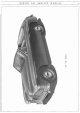
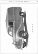
ENGINE D/2 Fig. 1. An exploded view of the engine. A. B. C. D. E. F. G. H. I. J. Valve rocker cover. Cylinder head assembly. Thermostat. Crankcase. Piston and connecting rod assembly. Push rod and tappet. Fan and water pump assembly. Camshaft and camshaft gear. Timing gear cover and timing chain. Starting nut, pulley, fan and dynamo belt. K. Crankshaft bearing caps. L. Oil pump and strainer assembly. M. Oil sump. N. P. Q. R. S. T. Flywheel. Exhaust manifold. Hot spot. Induction manifold.
ENGINE Connecting Rods The connecting rods are of "H" section steel stampings and employ detachable "Thinwall" bearings, the caps of which are secured by two H.T. steel bolts. The small end is fitted with a clamping bolt to secure the gudgeon pin. Torque wrench loading for connecting rod nuts 33 lbs. ft. (4. 562 kgm.). Gudgeon Pin Of tubular section, the gudgeon pin is grooved to take the connecting rod clamping bolt. At 70°F, (21. 1°C.) the pin should be a push fit into the piston boss.
D/4 ENGINE Expansion Plugs (or Welch Plugs) Four expansion plugs are fitted in the cylinder block. To remove a plug, drill a hole in the centre and lever out the plug with a screwdriver or other suitable tool. It is usual in fitting a new plug to coat the edge with a jointing compound before inserting. (The "bulge" must of course be on the outside when a plug is put in position.
ENGINE Oil Pressure Gauge The oil gauge gives an indication whether the oiling system is working properly. The normal pressure during ordinary running should be between 40-45 lb. per square inch (2.812 to 3.164 kg.jcm. 2), with a proportionate lower pressure when idling. The gauge should be observed when the engine is first started up after refilling the sump to check that the oi I is circulating and that the pressure is correct. It should also be kept under observation frequently during normal running.
ENGINE D/6 Remove the four long setscrews from the body, separate the bottom cover and lift out the driven gear. The driving gear is keyed to the spindle and will need to be tapped off. Remove the key from the spindle which can then be withdrawn from the pump body. Check that the driving key is a good fit both in the spindle and the driving gear. On reassembly, with gears in position and the bottom cover bolted up, the pump must be perfectly free from stiffness when rotated by hand.
D/7 ENGINE SERVICE OPERATIONS WITH ENGINE IN POSITION Valve Mechanism The overhead valve operating mechanism of this engine is of normal design, incorporating an oil feed under pressure from the main oil gallery to the rocker shaft, from which oil passes to each rocker and its adjusting screw. The complete rocker gear can be removed for examination without releasing the cylinder head. The valve rocker cover should first be removed and then the oil feed disconnected.
ENGINE D/8 Fig. 8. The right hand side of the power unit showing: 1. Air cleaner clamp bolt. 2. Valve rocker breather pipe. 3. Valve rocker cover. 4. Heater control valve. 5. Vacuum timing control. 6. Welch plug. 7. Distributor. 8. Cylinder drain tap. 9. Engine backplate. 10. Starter. 11. Dip stick. 12. Starter terminal. 13. Oil sump drain plug. 14. Oil filter. 15. Filter bracket. 16. Fan belt. 17. Dynamo pulley. 18. Sparking plug.
ENGINE grease to make a good joint and prevent sticking when the head is again lifted. Replace the rocker gear if this has been removed. Fig. 9. Tighten cylinder head nuts from the centre and work outwards in order shown. DJ9 Reset the tappets to . 015-in. and replace the valve cover. Replace the manifolds and carburetter making sure that good joints are made, connect up the radiator and by-pass hose, replace the sparking plugs and high tension wires. Refill the radiator.
D/10 ENGINE Removing and Refitting a. Valve Valve Seat Insert Removal With cylinder head removed a valve lifting tool, as illustrated in Fig. 11, can be used to compress the spring. Take away the circlip and the split cotters, then release the spring and remove the valve. Split the two halves of the spring cup between which there is a rubber seal. If this seal shows any signs of damage or perishing, it should be renewed as its object is to prevent excess oil entering the valve guide.
ENGINE D/11 Fig. 13. An exploded view of the cylinder head assembly. 1. Thermostat cover. 2. Cup washer. 3. Rubber bush. 4. Joint washer. 5. Joint washer. 6. Heater return pipe. 7. Manifold washer. 8. 9. 10. II. 12. 13. 14. Setpin and washer. Yoke washer. Hot spot. Joint washer. Cylinder head washer. Cylinder head. Thermostat housing. 15. Valve spring. 16. Thermostat. 17. Rocker arm. 18. Valve rocker cover stud. 19. Rocker shaft bracket. 20. Spacing spring. 21. Oil feed pipe and union.
ENGINE D/12 Valve Grinding Valve Guides For valve grinding a little grinding paste should be smeared evenly on the valve face and the valve rotated backwards and forwards against its seat, advancing it a step at short intervals, until a clean and unpitted seating is obtained. The cutting action is facilitated by periodically lifting the valve from its seat. This allows the grinding compound to repenetrate between the two faces, after being squeezed out.
ENGINE D/13 Fig. 16. An exploded view of the distributor drive. 1. Vacuum control union. 2. Distributor. 3. Clamp plate. 4. Clamp plate setpin. 5. Bolt for clamp plate. 6. Distributor housing. 7. Driving dog. 8. Main drive spindle. 9. Setpin for housing. 10. Spindle end. 2 8 H40. 293. B. The final position of the guide is shown in Fig. 15. Jt must stand ft-in. (17. 0656 mm.) above the valve spring recess in the cylinder head.
D/14 ENGINE However, with the gearbox in place a convenient method of obtaining the new firing position for No. 1 piston is to first of all remove all sparking plugs except No. 1. Using a piece of card, marked off in degrees, attached to the front bumper rotate the engine with the starting handle until T.D.C. of No. 1 piston, on compression stroke, is obtained.
ENGINE signs of carbon. Remember to thoroughly "blow-out" the plug after treatment under these conditions, in order to remove all traces of abrasive left inside. After cleaning, thoroughly examine the plug for cracked insulator or worn away insulator nose. Should either of these conditions be apparent a new plug should be installed. Carbon deposit on the threads of the plug should be carefully removed by using a wire brush, or, if available, a wire buffing wheel.
D/16 ENGINE Fig. 20. Illustrating the position of the engine before it is turned diagonally across the engine compartment and manreuvred clear of the car. cable from the carburetter by slackening the screw at the choke operating arm and withdrawing the cable. Disconnect the fuel pump flexible pipe at the pump union nut. Next release the heater outlet pipe from the rear of the engine, secured by a spring clip.
ENGINE D/17 and the bottom bolt of the starter flange. Also uncouple the spring connecting the clutch operating lever to the engine backplate. The car should now be lowered to the ground and the gearbox supported beneath the bellhousing, in a convenient manner, to keep it in its natural position. Withdraw the four setpins from each engine front mounting bracket and chassis side member. Now attach a suitable sling to the two engine lifting brackets, situated on top of the valve rocker cover.
D/18 ENGINE Before removing the radiator, first drain the cooling system by means of the radiator and cylinder block drain taps. If anti-freeze solution is present, this may be collected in a clean receptacle and used again. Disconnect the top and bottom hoses. Remove the temperature gauge bulb from the radiator header tank and unfasten the bonnet lock control cable from its catch, situated just in front of the radiator tap. Dismantle both horns from their brackets by undoing four nuts and bolts.
ENGINE D/19 OPERATIONS WITH THE ENGINE REMOVED It is possible to perform a few of the following operations with the engine in position. Before removal or replacement components must be cleaned but avoid the use of "fluffy" rags. It should be understood that reassembly of the various parts is a reversal of the dismantling procedure unless otherwise stated. Removing the Tappets Remove the valve rocker cover, slacken tappet adjustment and withdraw the push rods as described on page D/7.
~ N 0 tn z 0 H z tn I. 2. 3. 4. 5. 6. Fan. Fan pulley. Water pump. Water pump vane. Joint washer. Cylinder block. Fig. 28. 7. 8. 9. 10. 11. 12. The cylinder and crankcase assembly. Cylinder head stud. Breather pipe. Push rod. Tappet. Flywheel. Fuel pump. 13. Joint washer. 14. Joint washer. 15. Camshaft. 16. Joint washer. 17. Engine front plate. 18. Camshaft locating plate 19. Camshaft gear.
ENGINE D/21 T.DC
ENGINE D/22 Removing the Flywheel After taking off the Clutch (see Section E), the flywheel can be removed when the four nuts and the two locking washers have been released. When replacing the flywheel, see that the 1/4 timing mark is in line with the first and fourth throws of the crankshaft. Remove the lockwashers and setpins from the bigend and withdraw the cap. It will be noted that the bearing caps have thrust projections machined on them, which mate up with the recess on the big-end top half.
ti:I z 0 H z ti:I H40' 152. D. Joint washer. 2. Timing chain. I. l: } Crankshaft keys. 5. Crankshaft. 6. Thrust washer. 7. Centre main bearing. 8. Oil sump flange. 9. Oil pump spindle. 10. Oil sump. Fig. 11. 12. 13. 14. 15. 16. 17. 18. 19. 20. 32. Crankshaft and sump assembly. Oil pump body. Joint washer. Oil delivery pipe. Distance piece. Strainer body. Strainer cover. Joint washer. Cork sealing strip. Crankshaft gear. Oil thrower. 21. Crankshaft pulley. 22. Locking washer. 23.
ENGINE D/24 Fig. 33. An inverted view of the engine showing I. Oil strainer. 2. Joint washer. 3. Oil pump. 4. Oil delivery pipe. 5. Centre main bearing cap. 6. Centre main bearing. 7. Thrust washer. 8. Oil pump housing. 9. Release valve housing. 10. Release valve. 11. Spring. 12. Washer. 13. Cap nut. 14. Oil filter. 15. Oil delivery pipe union. 16. Cork sealing strip. Removing a Piston Remove the clamping bolt in the small end of the connecting rod, push out the gudgeon pin and remove the piston.
ENGINE peg formed on each pair fits into the bearing cap, Fig. 33, on replacement. New shell bearings, whether standard or undersize, should be fitted with their feathered projection correctly located. Handle the new shell bearing halves carefully as they have a very fine finish, and ensure that all dirt and D/25 grit is removed from the bearing caps and journal faces. Also check that the journal oil ways are free from foreign matter.
ENGINE D/26 DIAGNOSIS AND CORRECTION OF FAULTS Fault and Possible Cause Lack of Power Low or poor compression ... Defective or retarded ignition Incorrect valve clearance ... Choked jets ... ... ... Overheating ... ... ... Incorrect grade of oil ... ... Leaking joint washers ... High Fuel Consumption Retarded ignition ... ... Air cleaner to carburetter dirty Sticking valves ... ... Faulty sparking plugs ... Petrol leaks in general ... Carburetter incorrectly set ... Low Compression Leaking valves ... .
ENGINE Fault and Possible Cause D/27 Rectification Excessive Cylinder wear Incorrect grade of oil ... ... ... ... ... Lack of oil ... ... ... ... .. . .. . Dirty oil ... ... ... ... .. . .. . ... Overheating ... ... ... .. . .. . Air cleaner dirty (dust entering combustion ... chamber) ... .. . .. . ... ... ... Fuel mixture setting too rich ... ... Piston rings stuck in grooves or broken ... ... Badly fitted pistons ... ... ... ... ... Clean, and if oil bath type, maintain correct oil level.
SECTION E CLUTCH SERVICE JOURNAL REFERENCE NUMBER I DATE SUBJECT CHANGES -------i-------1---------------l-------------------------------l--------1--------------l-------------------------- - - ---l--------1--------------l---·--------------------
AUSTIN A40 SERVICE MANUAL E/1 CLUTCH GENERAL DATA Make Type Outside Diameter Total Frictional Area Thrust Bearing Type Number of Springs I. 2. 3. 4. Borg and Beck Single Dry Plate-Spring Drive ... 7i-in.(I8.4cm.) 20.03x2 sq. in. (129.2x2 cm. 2) Carbon Fig. 1. The clutch pedal Clutch pedal. Shaft oil nipple. Trunnion pin for lever. Return spring. 6 assembly, right-hand. 5. Clutch adjusting rod. 6. Lock nut. 7. Pedal bracket spindle. 8. Spindle oil nipple.
1:! N (') l' c:::: ~ (') ::r: I. 2. 3. 4. 5. 6. 7. 8. Release bearing and cup. Clutch cover. Release lever plate. Pressure plate assembly. Clutch plate with linings. Strut for release lever. Retainer spring. Anti-rattle spring. 9. 10. 11. 12. 13. 14. 15. 16. Fig. 3. An exploded view of the clutch. Release lever. Eye bolt. Release lever pin. Thrust spring. Nut for eye bolt. Release bearing retaining spring. Withdrawal fork. Shaft nut. 17. 18. 19. 20. 21. 22. 23. Shakeproof washer.
CLUTCH Fig. 4. The clutch pedal assembly, left-hand. A. Spring loaded link. B. Adjustment rod. C. Adjustment fork. D. and G. Dumb-bell universal joint lubricators. E. Brake pedal shaft lubricator. F. Clutch pedal shaft lubricator. The !-in. (19. 05 mm.) of free movement in the pedal will give a minimum clearance of lri-in. (2. 383.17 mm.) between the graphite release bearing and the release lever plate, thus preventing continual rubbing of the release bearing on the plate.
CLUTCH E/4 set and locked when the clutch is assembled and should not be altered unless the clutch has been dismantled and new parts fitted. Interference with adjustment will throw the pressure plate out of position and cause the clutch to judder. Dismantling, Assembling and Gauging the Clutch By using the clutch tool, a clutch can be quickly dismantled, reassembled and adjusted to a high degree of accuracy.
CLUTCH %T ~WEAR IN POSITION ~--~------1 ~~f~l~!'riALENGAGED PoSiTiON r -.,;:_RELEASE POSITION E/5 . 2~6MAX 2%+oR-Jsz L-------~~~~ Fig. 7. A sectional diagram of the clutch unit showing the main dimensions for assembly. Screw the centre pillar (3) into the base plate and slip the distance piece (2), (code 5 for 7i" clutch) over the pillar followed by the cam-shaped height finger (1).
SECTION F GEARBOX SERVICE JOURNAL REFERENCE NUMBER DATE SUBJECT CHANGES ---·--1----11-------1------------- -----------1--------1------------------
AUSTIN A40 SERVICE MANUAL F/1 GEARBOX GENERAL DATA Type: Synchromesh on 2nd, 3rd, Top Gear Conu·ol: Lever on Steering Column Number ot llears: 4 Forward, 1 Reverse Type of Gears: Oil Capacity: Gear Ratios: BEARINGS Layshaft, Front Diameter (inside) Type Clevite Bush .676-.680-in. (1.717-1.727 em.) Layshaft, Rear Diameter (inside) Type Clevite Bush . 677-. 683-in. (1. 719-1.734 em.) Helical Constant Mesh 3 pints: 3. 5 U.S. pints: 1. 68 litres 1st Speed 2nd Speed 3rd Speed 4th Speed Reverse ..
Fig. 1. This cutaway view of the gearbox clearly shows the assembly of the first and third motion shafts, also the laygears.
GEARBOX Fig. 2. Selector cable fitting. I. Securing nut. 2. Cable. 3. Dust cover. 4. Cable securing bolt (exploded view in inset). 5. Selector lever. 6. Cross shaft lever. c that is entailed is the removal of the dumb-bell shaft. This is done by pushing the dumb-bell inwards against the tension of the operating shaft spring when the other end will be free of the linkage. Pull the dumb-bell rearwards, clear of the operating shaft. By slackening the cable adjusting nut (see Fig.
F/4 GEARBOX DISMANTLING THE GEARBOX Drain Plug First drain the oil from the gearbox by removing the drain plug. The latter is situated beneath the gearbox at the left-hand side. Clutch Rod and Fork Remove the nut and washer from the end of the clutch operating shaft and lift off the operating arm. From within the clutch housing, release the nuts and spring washers from the clutch fork cotter pins, then tap the cotters from the operating fork.
GEARBOX laygear cluster and the two thrust washers will drop to the bottom of the box. These gears can only be lifted from the casing when the third and first motion shafts, together with their respective gears, have been removed. Third Motion Shaft The third motion shaft can now be withdrawn from the gearbox casing. Fig. 5. Removing the third motion shaft complete with gears.
2 H40. 262. B. I 51 @@f.~ '1)~ A @88 86 ~5 ~-87 © 6 ~~8 Fig. 7. The components of the gearbox.
Fj7 GEARBOX Caption for Fig. 7. I. 2. 3. 4. 5. li. 7. 8. 9. 10. II. 12. 13. 14. 15. IIi. 17. 18. 19. 20. 21. 22. 23. 24. 25. 26. 27. 28. 29. 30. 31. 32. 1st motion shaft nut. Locking washer. 1st motion shaft bearing. Ist motion shaft. Bush bearing. 3rd mot ion shaft. Locking peg spring. Locking peg. Speedometer wheel nut. Locking washer for nut. Washer. Speedometer wheel. 3rd motion shaft bearing. Housing for bearing. I st gear. 2nd synchroniser. Spring. Ball. Thrust washer. 2nd gear.
GEARBOX F/8 c HIO. 95. C. Fig. 9. Cone dimensions. A. Cone angle 5° 10'. B. Coarse thread turned with .015-in. lead. C. Cone diameter 2. 5-in. Fig. 8. Synchronising cone. A. Chamfer to be machined after cone is shrunk into position. B. Cone. C. Coupling adaptor. D. Constant mesh gear. Fahrenheit, expansion will allow the cone to be pressed home on to the gear without damaging the broaching and will be sufficiently close fitting to resist displacement in gear changing.
GEARBOX then pushed further along the synchroniser splines, followed by the coupling sleeve. As the coupling sleeve replaces the guide, the balls find their correct location in the coupling sleeve groove. F/9 E Layshaft Gears First locate the two thrust washers to the laygears, ensuring that the larger washer is at the front, and then place the gear cluster in the gearbox. Check that there is end play for the cluster gears of between .001 and .
GEARBOX. F/10 end of the layshaft must face forwards and the rear end must be flush with the gearbox casing. Reverse Gear Refit the reverse gear into the gearbox casing with the large gear to the rear. Oil the reverse gear shaft before inserting and secure the shaft with the locating pin and tab washer.
Fjll GEARBOX THE GEAR CHANGE MECHANISM Descrjption The gear change lever situated on the column operates both a cable and mechanical By depressing or lifting the change lever the either pulled or pushed, and thus turns the gate in the gearbox to select the desired gear. steering linkage. cable is selector Fig. 15. The gear change and oiling points. A. "C" lever pivot. B. D. E and J. Ball joint connections. C and F. Cross shaft bearings. G. Gearbox filler. H. Hand brake pivot. K. Selector return spring.
F/12 GEARBOX of the linkage. If wear occurs to the ball joints, then slight adjustment may be made at the joints themselves by releasing the split pin in the connector head and screwing up, slightly, the screw. After adjustment, relock the screw with a split pin. Lubrication Fig.l5 shows clearly the lubricating points of the gear change mechanism and if such lubrication is carried out regularly, namely at weekly intervals, there will be little likelihood of the controls failing or requiring adjustment.
SECTION G PROPELLER SHAFT SERVICE JOURNAL REFERENCE NUMBER I DATE I SUBJECT CHANGES
AUSTIN A40 SERVICE MANUAL Gf I PROPELLER SHAFT 2 4 Fig. I. Exploded view of the front end universal joint. I. Internal splined end of propeller shaft. 2. Dust cover. 3. Front half coupling. 4. Spider. 5. Oil nipple. 6. Needle bearing assembly. 7. Spring ring. Description The Propeller Shaft and Universal Joints are of Hardy Spicer manufacture (Fig. 1). The fore and aft movement of the rear axle and other components is allowed for by a sliding spline between the propeller shaft and gearbox.
PROPELLER G/2 SHAFT ends of the rings and extract with a screwdriver. If the ring does not come out easily, tap the bearing face lightly to relieve the pressure against the ring. Hold the splined end of the shaft in one hand and tap the radius of the yoke with a lead or copper hammer (see Fig. 3), when it will be found that the bearing will begin to emerge. If difficulty is experienced, use a small bar to tap the bearing from the inside, taking care not to damage the race itself.
PROPELLER wooden mallet, which will relieve any pressure of the bearings on the end of the journals. It is advisable to renew cork washers and washer retainers on spider journals, using a tubular drift. Replacing the Shaft Assembly Smear the propeller shaft splines with oil then slide SHAFT G/3 the splines into mesh with those of the gearbox third motion shaft.
SECTION H FRONT HUBS & INDEPENDENT FRONT SUSPENSION SERVICE JOURNAL REFERENCE NUMBER I DATE I SUBJECT I CHANGES ----1----1-------1---------- ----1---1------1---------------1---1------1----------
AUSTIN A40 SERVICE MANUAL H/1 FRONT HUBS AND INDEPENDENT FRONT SUSPENSION GENERAL Hub Bearings Inner R. & M. LJ 1-!, Double Purpose Ball Journal (Light), Size 1! X 2! X i~ -in. (31. 75x 69. 85x 17.46 mm.) Outer R. & M. MJ!, Double Purpose Ball Journal (Medium), Size! x2 X i~-in. (19. 05 X 50. 8 x 17. 46 mm.) Castor Angle 2! o Camber Angle 1o Swivel Pin Inclination 6t o Swivel Pin Thrust Bearing. Oilite Washer between two stainless steel washers. Swivel Pin diameter (top): . 686! to . 686!-in. (1.
H/2 FR0 NT H U BS AND INDEPENDENT SU SPE N SI 0 N Fig. 2. Front hub exploded. I. 2. 3. 4. 5. Hub cap. Axle nut. Axle nut cotter. Flat washer. Outer bearing. 6. 7. 8. 9. 10. Distance piece. Wheel stud. Hub. Inner bearing. Oil seal. split pin from the swivel axle locking nut. Using a box spanner and tommy bar remove the axle nut and ease the flat washer, under the nut, clear of the axle thread. The front hub can now be withdrawn by using an extractor.
FR0 NT H UBS AND INDEPEND ENT Place the swivel axle flat washer into position and screw the nut down finger tight. Spin the wheel and note the resistance, which at this stage is due to the oil seal. Then continue tightening the nut until a slightly increased resistance to the spinning of the wheel is noticed. The bearings are now pre-loaded and the split pin should be inserted to lock the nut. Screw the hub cap and its fipre washer on to the hub after first packing the cup with grease.
H/4 FRONT HUBS AND INDEPENDENT SUSPENSION H40. 162. A. Fig. 4. Components of the independent front suspension, 1. 2. 3. 4. 5. 6. 7. 8. 9. 10. 11. 12. 13. 14. 15. 16. 17. Shock absorber. Rear top wishbone arm. Clamping bolt for front top wishbone arm. Front top wishbone arm. Joining bolt for top wishbone arms. Upper trunnion link. Trunnion rubber bearing. Upper trunnion fulcrum pin. Fulcrum locking nut and cotter. Nut and washer for clamping bolt. Coil spring. Rebound rubber bumper.
FRONT HUBS AND INDEPENDENT SUSPENSION H/5 lower wishbone arms. Fit two short bolts into the vacant holes and secure with the nuts. Remove the slave bolts and fit the remaining two short bolts. See that all nuts are securely tightened. Removing the Suspension Jack the car, remove the wheel and the coil spring as already explained. Disconnect the steering side-tube from the steering arm by withdrawing the split pin and unscrewing the nut.
H/6 F R0 NT H UBS AND INDEPENDENT Wishbone Arm Screwed Bush Bearing: If it is found that the screwed bushes can be moved backwards or forwards on the fulcrum pin thread they should be renewed. Should new screwed bushes on the old fulcrum pin still permit end play, then renew the fulcrum pin. Shock Absorber: The cross shaft bearings of the double acting hydraulic shock absorber may have worn sufficiently to permit up and down or sideways movement of the cross shaft.
F R0 NT H UBS AND INDEPENDENT SU SPEN SI 0 N H/7 Replacing the Suspension Fit one rubber bearing to each of the suspension lower links, on the side which corresponds to the small hole in each of the frame brackets. Raise the links to the frame brackets, insert the fulcrum pins and slide the second bearing and special washer over the protruding end of each pin. Fit the nut but do not screw it home. Position the shock absorber and packing piece on its bracket and partly tighten the four setscrews.
H/8 FR0 N T HUBS AND IN DEPE N D EN T S U S P E N SI 0 N However, should the vehicle suffer damage to the suspension affecting these settings, the various angles must be verified to ensure whether replacements are necessary. Camber Angle: This is the outward tilt of the wheel and a rough check can be made by measuring the distance from the outside wall of the tyre, immediately below the hub, to a plumb line hanging from the outside wall of the tyre above the hub.
SECTION J STEERING SERVICE JOURNAL REFERENCE NUMBER I DATE SUBJECT CHANGES -----1-----1--·-----------------------------1-----------1------------------------1----1--------1----------------- -------'----------1-~-----------
AUSTIN A40 SERVICE MANUAL J/1 STEERING GENERAL DATA Type of Gear Cam and Lever Steering Gear Ratio (Saloon) 14 to I Steering Gear Ratio (Sports) 12 to 1 Bearings ... Ball Race and Felt Bush Adjustment Screw & Packwood Shims Diametel' of Steering Wheel 17-ins. (43.18 em.) Turning Circle (Cars) 37-ft. (II . 278 m.) Turning Circle (Commercials) 38-ft. (11. 582 m.) Track Toe-in l 6 -!-in. (1. 5875-3.175 mm.) Steering Connections Austin Ball Type Fig. 1.
J/2 STEERING Maintenance Lubrication of the oil nipples on the steering connections and swivel bearings is most important to maintain accurate steering. Approximately every 500 miles, use the oil gun and recommended oil to charge the following points with lubricant:- (a) Steering side and cross-tubes-6 nipples. (b) Lower wishbone arm outer bearing-2 nipples. (c) Swivel pin bushes-4 nipples. (d) Steering idler-1 oil filler plug.
STEERING J/3 a very fine adjustment. Adjustments should be made and checked regularly, otherwise undue slackness will cause a deformity of the ball pin thereby making further adjustment impossible. To make an adjustment, remove the split pin, lightly screw it back to the first alignment of the split pin hole and castellation. The ball should then be able to move freely in the socket. Always ensure that the rubber boot fits snugly in the groove provided for it in the tube end.
STEERING J4 phosphor bronze bushes. At its lower end the shaft incorporates a spline to take the double lever and a portion of screw thread to take the lever securing nut. The idler shaft is drilled for passing lubrication to the bearing bushes. No adjustment is necessary for this type of idler.
STEERING Jj5 it with the slotted nut, plain washer and split pin. Note that location marks are not necessary for this lever and shaft, but the clearance between the underside of the frame member and the rear machined face of the lever should be the same as for the lever fitted to the steering box shaft. The wheels must be in the straight-ahead position while these two levers are being fitted. Refitting the Side and Cross-Tubes First connect the two side-tubes to their respective steering arms and levers.
J/6 STEERING Fig. 9. Components of the steering box. 1. 2. 3. 4. 5. 6. 7. 8. 9. 10. 11. Felt washer. Circlip. Cork washer. Steering inner column. Top cover setpin. Rocker shaft adjusting screw. Adjusting screw locknut. Top cover. Joint washer. Steering gear housing. Rocker shaft arm. 12. 13. Peg for rocker arm. Steering gear bracket. 14. Setpin and washer. 15. Bracket clamp bolt. 16. Clamp bolt locknuts. 17. Ball cups for bearings. 18. Ball and cage assemblies 19. Cam. 20. Joint washer. 21.
Jj7 STEERING Dismantling The top cover plate should be removed after extracting the three securing setscrews. Turn the steering gear over and suitably support the top face leaving the rocker shaft free to be lightly tapped out using a soft metal drift. The following peg is a drive fit in the rocker and need not be removed unless showing an appreciable amount of wear. Adjusting the Gear The adjuster in the cover plate should be slackened by releasing the locknut and unscrewing the screw a few turns.
STEERING J/8 STEERING FAULTS If steering faults are not attributed to adjustment of the gear, they may fall into one of the following categories. Lost Motion The amount of lost motion reaches its maximum at either lock, but this is not normally felt at the steering wheel, since the geometry of the steering always tends to return the steering gear to the straight ahead position.
STEERING Loose Steering Loose steering is invariably attributed to end play of the inner column, which can be rectified by the removal of shims located behind the steering box end cover plate, in a manner already described. To check for this end float, disconnect the side and J/9 cross-tubes from the double lever and turn the steering partly to the right or left lock. Then with the steering wheel held to prevent it from turning, endeavour to turn the double lever.
SECTION K REAR AXLE SERVICE JOURNAL REFERENCE NUMBER I DATE SUBJECT CHANGES ----1------------------·-------------
AUSTIN A40 SERVICE MANUAL K/1 REAR AXLE GENERAL Type ! floating Oil Capacity 2t pints; 2. 7 U.S. pints 1. 28 litres Spiral Bevel Final Drive Crown Wheel Teeth: Saloon .. 37 36 Sports 43 Commercials ... Bevel Pinion Teeth 7 5.28:1 Ratio: Saloon Sports 5.14:1 6.14:1 Commercials ... Crown Wheel to Pinion Backlash . 005-. 008-in. (.127-.2032 mm.) BEARINGS Pinion Front: Make Timken or Skefko DATA Pinion Front (cont.
8. 9. 10. 11. 12. 13. 14. 15. 20 differential. Dust cover. Pinion flange. Joint washer. Bevel pinion front bearing. End cover bolt. Oil filler plug. Crown wheel bearing cap nut. lbl 8 Fig. 1. An exploded view of the Gear carrier. 16. Bevel pinion rear bearing. 17. Bevel pinion. 18. Pinion sleeve. 19. Bearing adjusting shim. 20. Bevel pinion lockwasher. 21. Bevel pinion nut. 22. End cover. 23 6 19 23. 24. 25. 26. 27. 28. 29. 30. H40. 233. C. Crown wheeL Differential pinion.
REAR AXLE K/3 7 14 I. 2. 3. 4. 5. Hub locknut and washer. Hub extractor. Extractor adaptor. Axle tube. Wheel stud and nut. II 8 13 12 Fig. 2. Using Service Tool18G 10 to extract a rear hub. 6. Hub. I I. 7. Brake shoe. 12. 8. Brake back plate. 13. 9. Brake shoe return spring. 14. 10. Brake shoe adjuster. and hub coincide. Then refit the brake drum taking the same precaution regarding the small hole, and ensuring that the drum is well home when inserting the screw.
REAR K/4 I. 2. 3. 4. 5. Axle shaft flange. Joint washer. Hub locknut. Hub lockwasher. Hub bearing. Fig. 6. 7. 8. 9. 10. AXLE 3. Rear hub assembly exploded, Oil seal. Hub casing. Back plate securing nut. Spring "U" bolt. Spring. The gear carrier unit can be withdrawn with the axle in position, although it is first necessary to remove the propeller shaft and then the axle shafts.
REAR AXLE K/5 Secure the carrier to a bench and prepare to remove the rear outer race first, using Service Tool18G 82 (see Fig. 6). This tool comprises the following parts: A body, a centre screw with a tommy bar, a wing nut and locating cone. In addition, there are three adaptors, lettered A, B and C. Place the body of the tool (3), Fig.
K/6 REAR AXLE weight is hung by a piece of cord from the circumference of the pulley, the pre-loading on the pinion bearings should be sufficient to prevent the pinion, and therefore the pulley, from turning. When a 3! lbs. (1. 58 kg.) weight is used the pulley should move under the load. This gives the bearings a pre-load of approximately 5 to 7-in.-lbs. (. 0575-.0806 mkg.). Refit the differential unit to the carrier, secure the bearing caps and place the complete assembly into the axle casing.
REAR AXLE K/7 parts are thoroughly cleaned it is rare to find that the crown wheel does not run true. The pinion mesh will be automatically correct for depth. Finally turn over the lockwashers for the crown wheel securing bolts. Carrier-To Replace Fig. 9. Replacing pinion front outer race. The unit is now fully dismantled and all parts should be checked for scoring and signs of wear. Wash all parts in paraffin, and ensure that they are clean when reassembled.
K/8 REAR When all the bolts have been tightened the axle shafts (which are interchangeable from left to right) can be threaded through the hubs and secured on to the four wheel studs as described earlier for the reassembling of the hubs. When connecting up the propeller shaft use new lockwashers under the four nuts. Replace the axle drain plug and refill the unit with oil.
SECTION L REAR SUSPENSION SERVICE JOURNAL REFERENCE NUMBER I DATE SUBJECT CHANGES
AUSTIN A40 SERVICE L/1 MANUAL REAR SUSPENSION GENERAL DATA SEMI-ELLIPTIC SPRINGS COMMERCIALS SALOON & SPORTS - ... Free Length ... ... Total Length ... ... Free Camber ... Laden Camber (negative) ... ... Deflection Number of Leaves ... ... ... ... ... ... ... 43~-in. (110.14-cm.) 44-in. (Ill. 76-cm.) 3!-in. (8. 89-cm.) 2-in. (5. 08-cm.) 5!-in. at 5-cwt. (13. 97-cm. at 254-kg.
REAR L/2 SUSPENSION B A. Free Length Fig. 2. Rear spring. B. Total length. Dismantling a Spring First remove the binding tape. Grip the spring in a vice, with the vice jaws against the top and bottom leaves, adjacent to the centre bolt. Free the two outside leaf clips by opening them out with a suitable punch and hammer. In the case of the two inside leaf clips, the riveted pin should be unscrewed, or if this is not possible the threaded end should be centre-punched and countersunk away with a drill.
REAR SUSPENSION Lf3 SHOCI{ ABSORBERS AND ANTI-ROLL BAR Description The shock absorbers .are Armstrong double-acting hydraulic, resistance being offered to the compression and to the recoil of the road springs. A special anti-roll bar is fitted across the rear of the chassis, being firmly attached to the shock absorber arms (see Fig. 4).
40!" f.+----21 ~· n Fig. 5. Dimensions given are primarily for checking purposes. H40. 110. B.
REAR SUSPENSION L/5 THE A40 SPORTS CHASSIS FRAME \.,14:) !-----~ ~-H • '-"I~ 1-"'N+--_ _ co_ ., ,_; lt E: "'0 ~p. tM '\( eo ~ ~0., ..<:: 0 I .... ~ t8 » ,I ] 'N -'\ N a- ''
SECTION M BRAI{ES SERVICE JOURNAL REFERENCE NUMBER I DATE SUBJECT CHANGES --------------l--------------1-----------------------
AUSTIN A40 SERVICE MANUAL Mjl BR.AI{ES GENERAL DATA Make Girling Type Hydraulic, Two-leading shoe front Pedal Free Movement ... ... i-in. (3 .175 mm.) Handbrake ... Pistol Grip Type Mechanical on Rear Wheels only Total Braking Area. (Saloon) (Sports) Inside Drum Diameter. (Saloon) (Sports) 83 sq. in. (535. 5 cm. 2) 129 sq. in. (832.2 cm. 2 ) 9-in. (22. 86 em.) 10-in. (25. 4 em.) Shoe Lining Width. (Saloon) (Sports) Ll-in. (31. 75 mm.) 1£-in. (44.45 mm.
Fig. 3. A general arrangement of the braking system showing both the full hydraulic and parking brake layouts. H40. 238. B.
BRAKES M/3 Front Brakes ~·-I (jJ) ~--2 ~-3 9~\ \ Q-4 13 "\ @-s @ -6 I. 2. 3. 4. 5. 6. 7. Fig. 4. Front brake back plate. Dust cover. 8. Bleed screw. Shoe plunger. 9. Bleed screw cover. Seal. 10. Spring washer. Seal support. 11. Retaining nut. Spring. 12. Cylinder Cylinder housing. connecting pipe. Bleed valve ball. 13. Shoe return spring. Fig. 5. Brake back plate and rear layout A. Rear brake adjuster. B. Bleed nipple. C. Balance lever oiling point. D. Brake fluid pipe. E. Handbrake cable. F.
M/4 BRAKES 1. 2. 3. 4. 5. 6. 7. 8. Adjustment unit. Back plate. Shoe and lining. Hydraulic cylinder. Rubber seal. Piston. Dust Cover. Housing nut and washer. Fig. 6. Rear brake back plate. 9. Bleed valve ball. 10. Bleed screw. 11. Expander tappet. 12. Setscrew. 13. Cover plate. 14. Tappet roller. 15. Roller wedge. 16. Cylinder housing. 17. 18. 19. 20. 21. 22. 23. 24. Seal spring. Seal support. Return spring. Shoe and lining. Adjustment wedge. Operating link. Adjustment housing. Setpin and washer.
BRAKES M/5 Carefully examine the various parts and renew any that appear worn or damaged. It is particularly important to renew any of the seals which are perished or worn. tightened up until a resistance is felt and then slackened back two clicks. The Master Cylinder This is the Girling compression type of cylinder and it is fixed to the chassis frame by two bolts. The assembly as shown in Fig.
M/6 BRAKES Rear Brakes: (1) Jack up the car and chock the front wheels. (2) Remove the wheels and brake drums. (3) It will be found quite easy to lift one of the shoes out of the slots provided in the adjuster links and expander tappets. Both shoes can be removed complete with springs. (4) Remove the two shoe return springs and replace if stretched or damaged.
BRAKES Note: Under no circumstances must excessive force be used when tightening the bleed screw. This process must now be repeated at each of the bleed nipples of the brake back plates. Always keep a careful check on the supply tank during the bleeding operations since it is most important that a full level is maintained. Should air reach the master cylinder from the supply tank, the whole of the bleeding operations will have to be recommenced. After bleeding, top up the supply tank to its correct level.
SECTION N TYRES & JACI{ING SERVICE JOURNAL REFERENCE NUMBER I DATE SUBJECT CHANGES ------l-------1--------------------------------- ------1------1------------1----------------
AUSTIN A40 SERVICE MANUAL N/1 TYRES .AND JACI{ING AMOST important factor in the road-worthiness of the car is systematic and correct tyre maintenance. The tyres must be able to sustain the weight of a loaded car and be able to withstand satisfactorily the vagaries of road conditions. Tyre pressures should, therefore, be checked at least once a week.
N/2 TYRES AND Changing a Wheel Remove the wheel disc and loosen the wheel nuts with the wheel brace. See that the hand-brake is firmly applied and if the car is on an incline, chock one of the wheels not affected. Jack up the car as required, remove the four wheel nuts and remove the wheel. JACKING 3. Commence to fit the second bead by pushing it into the well of the rim diametrically opposite the valve. Replacing the Wheel Lightly grease the studs and lift the wheel into position.
TYRES AND JACKING N/3 4. Mount the tyre on the rim whilst the soap solution is still wet. 5. Before inflating, be sure the tyre beads are clear of the well of the rim all the way round. 6. Inflate slowly until the beads are fully seated. 7. Remove the valve core to allow the tube to deflate completely. Do not disturb the beads of the cover. 8. Re-inflate to correct working pressure. This procedure must be followed whenever a tube is refitted.
N/4 TYRES AND Fig. 4. Front position for screw jack. A. Front suspension spring plate. B. Jack platform. C. Front suspension lower wishbone arm. The Under-Axle Type of Screw Jack This type of jack is used for the Commercial models. For the front wheels the lifting platform of the jack should be placed across the outer rim of the spring recess in the spring plate.
SECTION 0 ELECTRICAL EQUIPMENT SERVICE JOURNAL REFERENCE NUMBER I DATE I SUBJECT CHANGES ---------------------------------------- -----------1------------------------------- ---------1---~------------------- --------1-------1----------------- ----------1--------1-----------------------1--------11------------- ----------1---------1--------------
AUSTIN A40 SERVICE ELECTRICAL MANUAL 0/1 EQUIPMENT THE electrical equipment is designed to give long periods of service without need for adjustment or cleaning. The small amount of attention which is required is described under "Lubrication and General Maintenance".
ELECTRICAL 0/2 EQUIPMENT Austin A40 " Somerset " Wiring Diagram. \R.H.~'E'Ap~:,? MOTOR 9 r;; L.H. HORN .$ INTERIOR LAMP ~~38 HEATER MOTOR SWITCH TO LH. TRAFFICATOR -£3-18-----TO_R:,_.H.:._.T_R_A_F.:._FI.:._C_AT:...:O:..:.R:.....e=:3-:..::::--:::....:2~1.:._-_l: =1FUEL TANK RHEOSTAT 36 BR WN WITH BLUE 37 BROWN WITH WHITE 38 BROWN WITH GREEN 40 BROWN WITH BLACK 41 RED 44 IRED WITH WHITF Q -.¥1 ~24--E3-::24£§§~ ®::===5=7~~~~2i;2~~-)>-< J: 57 22?1 ~ ~ L.H. STOP &TAIL LAMP 41 L..fl.
ELECTRICAL EQUIPMENT 0/3 Austin A40 Commercial Wiring Diagram. ~~ 36 IGNITION COIL ~~N"-.----JL TANK R"'O'TAT fJ57 ~SL~22 ~41~ STOP & TAIL LAMPS El255 Fig. 2. The general circuit layout as employed on the A40 Commercial vehicles.
ELECTRICAL 0/4 EQUIPMENT Austin A40 Sports Wiring Diagram. \iL_, __ \_R_jL~~·"y_LA_M_P - ~([' _ _ _ _ _ _...., L~~ 4-- 57=---=-m_ :r 57 41 :::llE .., WIPER 44 7 IAMMETEj ~lm 62 PANEL 41 4===15J-·-4----------, 57~57-~57 41=---m=.±l=41- 44~ - '3d TI[~J~E -1' ~: ~frURE \.2;; SPEEDOMETER flAD!ATOR HMETER GAUGE r---1---44 ©:~=---·~ 17 VOLTAGE REG. & CUTOUT 24 Wfr fftiH ~ I IGNITION HI·BEAM W/'[~' 57 LIGHTING & -38 3 8 - r-::.0~ 57~-::;;;;;;;;:-] ...,.... _ ..57..
ELECTRICAL EQUIPMENT 0/5 EVERY 2,000 MILES Battery About every 2,000 miles or more often in hot weather, take out the filler plugs from the top of the battery. Check the level of the electrolyte in each cell and if necessary add distilled water to bring the electrolyte level with the top of the separators. The use of a Lucas Battery Filler will be found helpful when topping up, as it ensures correct electrolyte level, and also prevents distilled water from being spilled over the top of the battery.
0/6 ELECTRICAL EQUIPMENT the end of the contact breaker spring is anchored. Th1 lever can then be lifted off its pivot pin. After cleaning check the contact breaker setting. If the contacts are badly burned, they should be renewed. Replacement contacts must only be fitted i11 pairs. To remove the moving contact, follow the pro· cedure outlined above. To remove the plate carrying the fixed contact take out the two screws complete with spring washers and fiat steel washers.
ELECTRICAL EQUIPMENT 0/7 GENERAL INFORMATION BATTERY It is advisable to check the state of charge of the battery occasionally by measuring the specific gravity of the electrolyte in each of the ceiis by means of a hydrometer. Never leave the battery in a discharged condition for any length of time. Have it fully charged and every fortnight give it a short refreshing charge to prevent any tendency for the plates to become permanently sulphated.
ELECTRICAL 0/8 EQUIPMENT 14 13 A-----~®---12 I. Brush. l. Brush spring. 3. Thrust collar. 4. Commutator. 5. Field Coil. 10 Fig. 6. 7. 8. 9. 10. H40. 242. A. 10. The dynamo in exploded form. Distance collar. Driving end bracket. Yoke. Armature. Field terminal. The dynamo requires no other attention during normal service except for lubrication as described under "Every 12,000 miles".
ELECTRICAL Ammeter Readings When noting ammeter readings, it must be remembered that during daytime running when the battery is in good condition, the dynamo gives only a trickle charge so that the charge reading will seldom be more than a few amperes. A discharge reading may be given immediately after switching on the headlamps. This usually happens after a long run, when the voltage of the battery is high.
ELECTRICAL 0/10 Setting 10 deg. 20 deg. 30 deg. 40 deg. Temperature C. (50 deg. F) C. (68 deg. F) C. (86 deg. F) C. (104 deg. F.) Voltmeter Reading 16.1-16.7 15.8-16.4 15.6-16.2 15.3-15.9 If the voltage at which the reading becomes steady occurs outside these limits, the regulator must be adjusted. Shut off the engine, remove the control box cover, release the locknut (A) Fig.
ELECTRICAL reduce the setting, testing after each adjustment by increasing the engine speed until the cut-out is seen to operate, and noting the corresponding voltmeter reading. Tighten the locknut after making the adjustment. Mechanical Setting As in the case of the regulator, adjustment of the mechanical setting of the cut-out should not be necessary in normal service.
ELECTRICAL 0/12 EQUIPMENT l:i40. 166. A. A. B. C. D. E. Cover band. Brush spring. Brushes. Through bolt. Terminal nuts. Fig. 15. The starter in exploded form. L. Retaining ring. F. Terminal washers. M. Control nut. G. Terminal post. N. Sleeve. H. Split pin. P. Restraining spring. J. Shaft nut. Q. Bearing bush. K. Main spring. R. Bearing bush. Testing on the vehicle In the following test it is assumed that the battery is in a charged condition. Switch on the lamps and operate the starter control.
ELECTRICAL EQUIPMENT 0/13 Dismantling the Starter Motor Take off the cover band at the commutator end, hold back the brush springs and take out the brushes from their holders. Remove the terminal nuts and washers from the terminal post on the commutator end bracket. Unscrew and withdraw the two through-bolts and take off the commutator end bracket. Remove the driving end bracket complete with armature from the starter yoke. Reassemble by reversing the above procedure. Fig. 16.
0/14 ELECTRICAL EQUIPMENT H.T. Cables: The high tension cables must be carefully examined, and any which have the insulation cracked, perished or damaged in any way, must be replaced by 7 mm. rubber covered ignition cable. The method of connecting the cables to the coil is to thread the knurled moulded nut over the cable, bare the end of the cable for about !-in. (6. 35 mm.), thread the wire through the washer removed from the end of the original cable and bend back the wire strands.
ELECTRICAL EQUIPMENT 0/15 Remove the fixing screw from the top of the horn and take off the cover. Detach the cover securing bracket by springing it out of its location. Using a pair of 4 B.A. spanners, slacken the locknut below the fixed contact and rotate the adjusting nut until the contacts are just separated. Then turn back the adjusting nut about half a turn and measure the current taken by the horn when the horn push is operated. This current should be between six and seven amperes.
ELECTRICAL 0/16 EQUIPMENT Replacement of Blade To remove the blade, pull the arm away from the windscreen and disengage the blade by swivelling it upwards. To clip the new blade in position, insert the curved "wrist" at the end of the arm into the slot in the back of the blade.
ELECTRICAL EQUIPMENT 0/17 (3) Position the replacement Light Unit between the unit rim and seating rim taking care to see that the die cast projection at the edge of the light fits into the slot in the seating rim and also that the seating ring is correctly positioned. Finally secure in position by means of the three fixing screws. 2 Cars for Export to U.S.A. 5 MC. 66. A. 4 Fig. 25. Headlight glass assembly. 1. Vertical adjustment screw. 2. Rubber dust excluder. 3. Front rim. 4. Rim securing screw.
ELECTRICAL 0/18 EQUIPMENT (v) Solder the core of the Red and Black cable to one of the remaining spring contacts and fit the contact in the recess of the adaptor marked "Pass". (vi) Solder the core of the Blue cable to the remaining spring contact and fit the contact in the recess of the adaptor marked "Drive". (vii) Finaily fit the sealed beam unit assembly to the lamp body, as already described. 2 Fig. 28. Removal of the glass of the stop-tail lamp. 3 MC. 64. A. Fig. 27. Headlamp beam setting. 2.
ELECTRICAL EQUIPMENT 0/19 LOCATION AND REMEDY OF FAULTS Although every precaution is taken to eliminate all possible causes of trouble, failure may occasionally develop through lack of attention to the equipment, or damage to the wiring. The following pages set out the recommended procedure for a systematic examination to locate and remedy the causes of some of the more probable faults.
0/20 ELECTRICAL 2. Battery overcharged (a) This will be indicated by burnt-out bulbs, very frequent need for topping-up of battery, and high hydrometer readings. Check the ammeter readings when the car is running steadily with a fully charged battery and no lights or accessories in use, the charge reading should be of the order of only 3-4 amperes. If the ammeter reading is in excess of the value, it is advisable to have the regulator setting tested, and adjusted if necessary by a Service Depot or Agent.
SECTION P BODYWORI{ SERVICE JOURNAL REFERENCE NUMBER DATE SUBJECT CHANGES
AUSTIN A40 SERVICE MANUAL P/1 BODYWORI{ THE careful maintenance of the bodywork, both internally and externally, is of primary importance if the car is to retain its appearance and comfort. The periodical attentions briefly indicated in the following paragraphs should therefore be undertaken as regularly as possible. Care of the Bodywork Enamel The A40 bodies are finished in a synthetic enamel which gives a fine glossy finish to the bodywork.
BODYWORK P/2 1!40. 273, A, Fig, 1. The bonnet surround assembly showing at 1. The grille and its method of fixing. 2, 3, and 4. The side securing brackets. 5. The rear securing positions. 6. Bonnet top hinge. Front Wing and Baffles Each front wing has its rear baffle plate welded to it, thus the dismantling of a wing from the body is quite simple. Six wing brackets are secured to the flitch plate by five bolts and one setpin. A set of seven setpins holds the baffle plate to the scuttle.
BODYWORK rubber cushion. By peeling back this rubber, four screw type headed bolts are revealed. Withdraw these from their nuts accessible beneath the wing. The remaining seven securing points are nuts and bolts passing through the wheel arch, six of which are accessible within the luggage compartment. To gain access to the seventh, remove the quarter casing situated above the wheel arch and partially obscured by the rear seat squab. The operation is made easier by the removal of the seat squab.
P/4 BODYWORK @ @ @ ® @ @ @ @ @ @) @ ® H40. 278. A. Fig. 6, The front bumper with stay arms exploded. Valance Panel Situated beneath the fascia and dash there is a tray called the valance panel. It becomes necessary to partially withdraw this valance when, for some reason, the heater demister pipes have to be disconnected.
BODYWORK P/5 H40. 279. A. Fig, 8. The rear bumper with stay arms exploded. Windows and Doors Front Door Windows: Before it is possible to renew a window, should the necessity arise, the window winding mechanism must be exposed. To do this the window frame moulding securing screws and cup washers must be extracted when the moulding can be taken from the door. In addition to this the door inner casing must be dismantled.
BODYWORK P/6 9 H40. 294. A. Fig. 10. The near-side front door exploded. 2{! ~ a{':' 4 Q) ~ 12 5 Fig. 11. The near-side rear door exploded.
P/7 BODYWORK 1. 2. 3. 4. 5. Door shell. Window glass. Window rear channel. Window moulding. Louvre assembly. Door lock mechanism. Window winding handle. Door opening handle. Window winding mechanism. 5. Door inner casing. 1. 2. 3. 4. 6. 7. 8. 9. 10. Caption for Fig. 10. Window front channel. Upper hinge. Lower hinge. Door lock exploded. Window winding handle. Caption for Fig. 11. Arm rest (door closing handle). Window moulding. Louvre assembly. Door shell. 10. Window rear channel. 6. 7. 8. 9.
BODYWORK P/8 H40, 173. A. Fig. 13. The sliding roof locking mechanism. A. Slide bar. B. Locking bar. C. Keep-plate. D. Adjusting screw. E. Cranked lifting rod. involves the simple process of levering the chrome strip away from the bodywork. However, care should be taken to ensure that no harm comes to the paintwork. All chrome strip is secured in this manner with the exception of the rear wing protection plates. These are secured through the wing by three setscrews.
BODYWORK The rearward movement of the locking-bar rotates the cranked rod (E), which passes through the channel and across the sliding roof panel. The hooked ends of the rod lift on the brackets in the water trough at each end of the roof opening, when the roof is unlocked. This turning and lifting movement of the hooked ends keeps the panel flush with the main roof. The slide bar is secured to a bracket mounted in the main roof and remains in position when the sliding panel is removed.
BODYWORK P/10 dib dTh OFF DEHIST WARM DEFROST HOT DEFROST OFF
BODYWORK (c) If the correct operation in (a) or (b) is not being obtained, adjustments must be made as for (c) in "Heating/Ventilating Control Adjustment". Heater Removal Before withdrawing the four setpins which hold the heater to the scuttle, there are other items of heater equipment that have to be disconnected. The Bowden cables operating the air valve and demister valves should be disconnected at the heater unit.
Fig. 16. Illustrating the main body mounting points on the chassis, numbered from 1 to 6. Inset shows points No. 6 enlarged.
BODYWORK 15. Under the floor carpet at each side of the body are three small panels and one each side of the gearbox cover. With these panels removed, access is gained to the heads of the body holding down bolts. At each side of the body there are five sets of nuts, bolts and washers and rubber pads for securing the body, through brackets, to the chassis. Further, through the chassis cross bracing members each side of the gearbox P/13 there is one more nut, bolt, washer and rubber pad.
BODYWORK P/14 If the inner wing is to be removed, both the inner and outer wings should be removed as a complete unit by detaching the five front apron to wing bolts, the six bolts securing the inner wing to the flitch plate and the rear baffle plate bolts and outer wing bolts to the scuttle mentioned previously. The wing assembly can be removed complete when the head and side lamp cables have been disconnected at their snap-on connectors.
BODYWORK P/15 6------;-- H40. 301. A. Fig. 19. The off-side front door exploded. 1. 2. 3. 4. Lower hinge. Door inner casing. Door shell. Upper hinge. 5. Louvre assembly. 6. Door moulding. 7. Door lock mechanism. 8. Window front channel. 9. Window glass. Fascia Panel Before the fascia panel can be removed, the instrument panel, starter and choke control wires must first be released. The instrument panel is held to the fascia by four setpins visible on the face of the instrument panel.
P/16 BODYWORK The heater motor bearings are packed with lubricant when the unit is first assembled and servicing should not normally be necessary. Doors and Windows Door Removal: The upper and lower hinges of the front doors are each held in place by three setscrews. With these removed, the door can readily be detached from the bodywork. Door Windows: Before either the window or the louvre can be withdrawn, the door inner casing must be detached.
P/17 BODYWORK (see P/11) with the exception that the exhaust tail pipe must be released from the rear of the body. The body main securing points are illustrated in Fig. 16, page P/12, and it should be noted that the body mounting point numbered (5) is not used for these vehicles. Note: On the Pick-Up model the truck body can be separated from the cab, either before or after removal, by taking out the seat squab and extracting the nuts and bolts holding the two parts of the body together.
P/18 BODYWORK Grille The grille is secured to the shroud at eight points behind the opening. Two cheese head screws, visible on the top face of the bonnet catch plate, screw into tapped holes in each central grille supporting pillar. At the base of the supporting pillars, which are angled through 90°, there are two nuts and bolts holding the grille to the front of the shroud. Access to these nuts and bolts can only be gained by removing the front bumper. 1 Fig. 22. Securing Points of Radiator Grille.
BODYWORK A. Bumper main arm. B. Rear bumper. C. Clamping arm. Fig. 25. Showing the Bumpers and their Securing Brackets. 1. Screw thread setpin. D. Front bumper. E. Number plate bracket. 2. Plain holes for bolts. F. Front bumper bracket. 3 and 4. Main securing points to chassis. 1. Disconnect the direction indicator cable. To do this first remove the small panel, provided for the purpose, in the door rear pillar. This panel is held in place by two metal thread screws. 2.
P/20 BODYWORK Boot Lid Remove the boot lid by undoing the single bolt, with nut and washer, which secures the supporting stay to the boot lid bracket. From each hinge, on the under side of the boot lid, unfasten the two nuts and take off the flat and spring washers when the lid can be lifted clear of the bodywork. · Fig. 28. Rear Panel. 1. Holes in top flange for "pop" rivets. 2. Side securing points. 3. Bottom flange holes for "pop" rivets. 4. Countersunk screw holes. Fig. 27.
BODYWORK P/21 H40. 222. A. Fig. 30. Illustrating the Fitting of the Clatonrite Seal. A. Fitting the Windscreen into its channel. C. Inserting the filler strip. D. Compressing the ends of the filler strip. B. Lubricating the filler strip channel. one should be fitted. Allow an extra eighth of an inch for every estimated foot of seal required. This will ensure weatherproof joints and a good fit all round the 2 3 4 5 6 7 H40. 223. B. Fig. 31. Cross Section of Sealing Strip. 1. Windscreen. 2.
P/22 BODYWORK 1. Screws holding control knob panel. 2. Screws securing glove box to fascia Fig. 32. The Fascia. 3. Side securing points of fascia. 4. Glove box hinge bolts. is held by a grub screw, slacken it and remove the control knob, also unscrew the chrome ring securing the heater switch to the fascia. The remaining control knobs are held by spring-loaded plungers. The control knob panel is held in position by three screws, one each side and one above the ignition switch. See 1, Fig. 32.
1 2 1. 2. • Door shell. Louvre assembly. ~1~~~~ ". ~ -~~ Fig. 33. Exploded View of Door. 3. Window glass. 4. Door lock mechanism. 3 5. 6. 5 ® 0 @"' 0 ,:.o~ H40. 220. A. Window winding mechanism. Door inner casing. I .
P/24 BODYWORK Remove the window glass stop by releasing one setpin and washer, undo the two nuts and bolts that secure the window glass stop bracket to the metal casing and then extract the bracket. Now wind up the window to its full extent when it will be found that it can be lifted out quite easily. To replace a window glass, lower it into the aperture in the top of the door, spring in the two rollers into their respective channels, which are attached to the pane of glass.
BODYWORK P/25 seat cushion and then tip forward the backrest, release the locking handle and slide the seat rearward out of its runners. Each seat runner is secured to the floor by four setpins. The rear seat is of the "drop-in" type and is easily removed. To take out the rear seat squab, first release the press stud fastening midway on the hood lip. Tip the squab forward and withdraw two screws from each hinge at the base of the squab.
P/26 BODYWORK -----.
BODYWORK The petrol tank and disconnect the feed pipe at the base of the tank. Release the wires to the rear lights, then extract the cables from the rear panel on the underside of the car. Disconnect the wire to the petrol tank gauge unit. Following these preliminary operations, the body main securing points can now be released. These are clearly shown in Fig. 37, being the same at each side.
SECTION Q SERVICE TOOLS SERVICE JOURNAL REFERENCE NUMBER ~-----~ I CHANGES SUBJECT DATE ------ ---------1--------------------- ------------ ----------------- --~- -~----- ------------ ------------------ ----~-- ----- --~-·- -----~ ----- --------~---~----------~- ----------------------------------------~--~------------- ----------1-~------1--------------- ----- --~---1--·-------1---------------- ------ ~----1--·------ -------~----1--- --------- ------------~----- ~------·--------
AUSTIN A40 SERVICE MANUAL Q/1 SERVICE TOOLS THE service tools listed in this section are those referred to in the text of the manual. Service efficiency is entirely dependent on the correct use of the right tool for the work in hand. The tools listed can be obtained from the Austin Service Department. ENGINE .AND CLUTCH TOOLS I Crank gear extractor, fan and dynamo pulley extractor 180 2 .ST. 1Q9. A. Valve seat cutter Pilot Handle 180 25 18026 180 27 ST. 101. A.
SERVICE TOOLS Q/2 Starting nut spanner lSG 98 lSG 120 Valve seat insert extractor ... Tool illustrated on page D/10. Dummy first motion shaft ... Main bearing cap extractor Valve grinding-in tool Tool illustrated on page D/12. 18G 39 18G 42 lSG 29 ST. 84, A, Crank gear drift, fan and dynamo pulley drift 18G 99 Clutch assembly tool Tool illustrated on page E/3. Piston ring clamp 18G 55 18G 1 ST. 86. A. Front cover locating tool ...
SERVICE TOOLS Q/3 GEARBOX TOOLS Selector rod guide ... Tool illustrated on page F/10. First motion shaft assembly drift Tool illustrated on page F/9. First motion shaft nut spanner Front hub cap spanner 18G41 18G 4 18G5 ST. 89. B. Synchromesh assembly tool Tool illustrated on page F/8. 18G 40 Dummy layshaft 18G 6 FRONT SUSPENSION HUB TOOLS ST. 114. A. Coil spring compressor Front hub extractor Tool illustrated on page H/1.
Q/4 SERVICE TOOLS ST. 193. A. Wrench for swivel axle hush reamers ... ... 18G 68 Suspension checking plate 18G 56 Hub outer bearing remover 18G 7 Swivel axle bottom bush reamer Swivel axle top bush reamer . 18G 65 18G 64 Suspension assembly fixture .. 18G 89 REAR AXLE TOOLS ST. 82. A. Rear hub spanner ... 18G 23 Front and rear bevel pinion outer race remover and replacer ... 18G 82 Tool illustrated on page K/5. Bevel pinion flange wrench Propeller shaft wrench ... ...
SERVICE TOOLS Differential case bearing extractor Q/5 18047 Bevel pinion rear bearing inner race extractor and replacer Rear hub assembly and outer bearing drift 1809 18012 Bevel pinion flange drift See page Q/2. 180 1 Bevel pinion flange extractor See page Q/ 1. 1802 STEERING AND CHASSIS TOOLS Steering wheel extractor Tool illustrated on page J/7. ... 180 70 Steering arm extractor Tool illustrated on page J/7. ...
Q/6 SERVICE TOOLS THE OIL GUN THE gun, as supplied, is used for forcing lubricant through the nipples. Charge the gun by unscrewing the end cap and fill to its capacity. A. B. C. D. E. F. Oil gun nozzle. Piston and telescopic ram. Outer case. End cap. Adaptor. Components of the nozzle. H70. 108. A. Oiling Technique Always make sure that the nipple on the chassis component about to be lubricated is clean before applying the gun.
AUSTIN A40 SERVICE MANUAL P.ART NAME ALTERNATIVES I Engine Controls .. .. Gearbox . . Axle Steering .. .. Electrical .. .. .. .. Austin Part Name Alternatives .. .. Gudgeon Pin Scraper Ring Welch Plug Oil Sump .. .. .. .. .. .. Piston Pin. Small End Pin . Wrist Pin Oil Control Ring Expansion Plug. Core Plug. Sealing Disc Oil Pan. Oil Reservoir .. .. .. Strangler. Easy Starting Device Choke .. Gear Lever . . .. Change Speed Fork .. First Motion Shaft .. Layshaft .. . .
AUSTIN A40 SERVICE MANUAL s SERVICE FACILITIES HE following are the official addresses of the Austin Motor Company Limited and their Subsidiary Companies overseas, to whom all Service correspondence in those areas should be addressed.
SECTION T RECOMMENDED LUBRICANTS SERVICE JOURNAL REFERENCE NUMBER I DATE I SUBJECT CHANGES -------1---1------------------------------1----------1---------- L---~---1------1----------------- ------1----------------------------- -----------1------------------------
Wakefield Oilit Wakefield Castrollo Castro! Penetrating Oil Shell X.IOO. 20 Shell Donax U Shell Donax P Mobil Handy Oil Mobil Upperlube Mobil Spring Oil Distributor and Oil Can Upper Cylinder Lubrication Laminated Springs Esso Penetrating Oil Esso Upper Motor Lubricant Esso Handy Oil Energol Penetrating Oil Energol U.C.L. ) 0 ) temperatures use S.A.E. 80 E.P. Lubricant. § Oil Nipples: For high temperature climates the grease as shown for hubs can be used.
Shell Retinax A Shell X.IOO. 20 Shell Donax U. Shell Donax P. Mobil Hub Grease Mobil Handy Oil Mobil Upperlube Mobil Spring Oil Front Wheel Hubs Distributor and Oil Can Upper Cylinder Lubrication Laminated Springs ----- Castro! Hi-Press Shell Spirax 140 E.P. Mobilube GX 140 Rear Axle, Steering Box, and Oil Nipples Energol Penetrating Oil Esso Penetrating Oil Castro! Penetrating Oil Hydraulic Brakes:-Use Girling Brake Fluid (Crimson) only.
c Oil Can & Top-up the Engine Reservoir. Steering Connections (7). Swivel Axles (4). Front Suspension Lower Joint (2) Rear Spring Shackles (2). Brake Linkage, Carburetter Control Joints, Gear Change Control Joints. Oil Can Examine Oil Gun Oil I I F G H E D Brake Balance Lever (1). Hand-brake Pivot (1). Clutch Pedal (1). Brake Pedal (I). Steering Column Top Bush. Brake Fluid Supply Tank Level. Front and Rear Shock Absorbers. Check for leaks. I Top-up Drain and refill Engine Reservoir.
3 ENGINE OIL As may be seen from the illustration, oil from the sump is pumped gear and overhead valve mechanism. After circulation, surplus oil is · 1. Release valve. 2.
CIRCULATION through the by-pass filter to the various bearings, the camshaft drained from the rocker gear via the push rod holes to the sump. gauge. 3. Oil feed to each tappet.
Hand-brake, Pedal, and Carburetter Control Joints. Carburetter Piston Reservoir. Brake Linkage. Gear Change Control Joints. c Oil Can *See Every 10,000 Miles-Dynamo Bearings Page XX. Steering Connections (7). Swivel Axles (4). Front Suspension Lower Joint (2) . Rear Spring Shackles (2). B Oil Gun Top-up the Engine Reservoir. A Oil Examine F H I G Oil Can I E I D Oil Gun I Oil Oil J K I 0 N I ML I Examine I ·Oil Can Grease Oil Oil Gun Top-up the Steering Box (5,000 miles).