
Owners Manual


GEARBOX
F/3
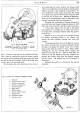
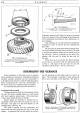
Fig. 2. Selector cable fitting.
I. Securing nut.
2.
Cable.
3.
Dust
cover. 4. Cable
securing bolt (exploded view in inset).
5.
Selector
lever.
6.
Cross shaft lever.
that
is
entailed is the removal
of
the dumb-bell shaft.
c This is done by pushing the dumb-bell inwards against
the tension
of
the operating shaft spring when the other
end will be free
of
the linkage. Pull the dumb-bell rear-
wards, clear
of
the operating shaft.
By
slackening the cable adjusting
nut
(see Fig. 2),
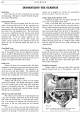
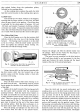
Fig. 3.
1.
Hinge pin.
2.
Hinge pin
rubber
bushes.
3.
Rubber
mounting-side.
4.
Rubber mounting-lower.
5.
Mounting support.
6.
Buffer plates.
7.
Rubber
buffers.
"
8.
Chassis stabiliser bracket
9.
Distance tube.
10.
Shakeproof washers.
II.
Forked
stay rod.
and unscrewing the union locknut, the change speed
cable can be withdrawn from the gearbox operating arm,
which is situated on the underside
of
the gearbox. To
save bending the cable casing, disconnect the casing
at
its upper union
nut
and
then
turn
the casing and cable
to one side, out
of
harm's way. Release the fingertight,
union cap
of
the speedometer cable,
at
the gearbox end,
and then extract the cable from the gearbox.
Dismantle the connecting rod between the gearbox
cross shaft lever and the gear change mechanism
at
both
ends, this
rod
is
secured by a ball and socket connection.
At this stage, support the rear end
of
the engine
with packing or a suitable jack to relieve the load on
the engine front mounting brackets when the gearbox
becomes free.
Release the four nuts, bolts and washers securing
the gearbox mounting bracket to the chassis, also
remove the three stabiliser securing nuts, bolts and
washers.
Commencing
at
the bottom
of
the gearbox, remove
the various securing bolts
or
setpins holding the clutch
housing to the engine rear flange. Note: Two
of
these
fixing points hold the starter in place. Before finally
releasing the top two securing points, support the
gearbox from inside the car. Then
as
these bolts are
removed, lower the engine a little
and
withdraw the
gearbox first motion shaft from the flywheel bearing
and the clutch. The gearbox can now be lowered
to
the ground.
Replacing the gearbox is a reversal
of
the removal
procedure.
H40.
237. A.