
Owners Manual


F/4
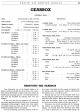
GEARBOX
DISMANTLING
THE
GEARBOX
Drain Plug
First drain the oil from the gearbox by removing
the drain plug. The latter is situated beneath the gear-
box at the left-hand side.
Clutch Rod and Fork
Remove the nut and washer from the end
of
the
clutch operating shaft and lift off the operating arm.
From within the clutch housing, release the nuts and
spring washers from the clutch fork cotter pins, then tap
the cotters from the operating fork. The clutch shaft
may now be withdrawn from the housing, there being
no need to disengage the circlip and washer from its
left-hand side.
If
the car being operated on has
left-hand drive, then the clutch shaft circlip and
washer will be situated
on
the right-hand end
of
the
shaft and must be removed before the shaft can be
extracted.
Cross Shaft Lever
The cross shaft lever
is
positioned on the right-hand
side
of
the gearbox
if
the car has right-hand steering,
and on the left for left-hand driven models. A cotter pin,
spring washer and nut secure the lever to the shaft. After
the
nut
and washer have been removed the pin may be
tapped out and the lever lifted off the shaft.
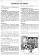
Front Cover
Release the front cover situated within the clutch
housing by removing its seven nuts and spring washers.
At this stage
of
dismantling do not attempt to re-
move the cover and joint washer. The operation will
prove easier when the shift fork selector rods are tapped
forward, thus pushing the cover away from the casing.
Side Cover and Change Speed Gate
Holding the side cover
in
place are nine setpins
with spring washers. The change speed gate
is
located
by its two rounded ends,
of
the outer face, fitting into
recesses in the gearbox side face. To release the gate
from position
it
merely needs a gentle prising outwards
with the aid
of
a screwdriver.
Selector Arm and Cross Shaft
The selector arm
is
secured to its operating lever by
a nut and tab washer. Bend back the tab
of
the washer
and release the securing nut. To assist the latter opera-
tion,
it
is necessary to withdraw the operating arm
as
one works at the nut, thus giving the nut removal
clearance.
Lift out the selector arm and then withdraw the
cross shaft from its position, leaving the oil seal and felt
washer in the housing.
If
need be, the oil seal and felt
washer can be tapped out. Extract the speedometer
pinion and sleeve from the rear cover.
Selector Rods, Forks and Rear Cover
Withdraw the eight rear cover setpins and slide the
cover clear
of
the third motion shaft.
Using a soft metal drift, tap forward, for a short
distance, each
of
the three selector rods and prise out
the keys which are fitted to prevent the rods from turning.
Now drive each selector
rod
forward clear
of
the
forks and extract them from the front
of
the gearbox.
Care should be exercised
in
order that the spring loaded
locating ball
of
each fork
is
not lost during this operation.
Lift out the three bronze forks, noting carefully
their respective positions to assist reassembly. Fitted
behind the third speed fork
is
a distance piece, which
must be retrieved from the box when removing the
respective fork.
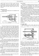
Reverse Gear
A lug, which is an integral
part
of
the main casting,
locates the forward end
of
the reverse gear shaft. To
secure the shaft
in
position, a setpin is screwed through
the lug locating in the shaft. The setpin is locked by a
tab washer. Straighten the tab washer, release the setpin
then tap forward and remove the reverse gear shaft.
Lift out the reverse gear.
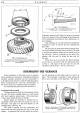
Layshaft and Laygears
Using a bronze or other soft metal drift, drive the
layshaft forward and
out
of
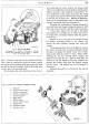
the gearbox, when the
Fig. 4. A cutaway view
of
the left-hand side
of
the
gearbox with the side cover removed.