
Owners Manual
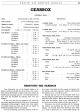


GEARBOX
F/5
laygear cluster and the two thrust washers will drop
to the bottom
of
the box. These gears can only be
lifted from the casing when the third and first motion
shafts, together with their respective gears, have been
removed.
Third Motion Shaft
The third motion shaft can now be withdrawn from
the gearbox casing.
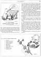
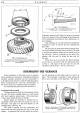
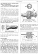
Fig. 5. Removing the third motion shaft complete
with gears.
To remove the gears from the third motion shaft,
first slide off the third and top speed synchroniser
assembly. Then depress the small spring loaded steel
plunger, which locates the splined washer
at
the forward
end
of
the third motion shaft, and turn the washer into
line with the splines
of
the shaft. A peg spanner is a useful
tool for turning the splined washer, the latter having two
holes in its upper surface for turning purposes. The
third and second speed constant mesh gears, together
with their common phosphor bronze sleeve (made solid
by
a common thrust washer), can now be pulled over
the steel plunger and
so
clear
of
the third motion
shaft. Remove the steel plunger and its spring from
the shaft.
Next remove the splined washer separating the
second speed constant mesh gear assembly from the first
gear unit, and then slide the first gear assembly free
of
the third motion shaft.
To release the speedometer wheel from the third
motion shaft, straighten the tab washer and unscrew
its securing
nut
and slide the speedometer wheel off
the shaft. The third motion shaft bearing can be
separated from its housing after the unit is prised from
the shaft.
If
it
is desired to dismantle the top and third speed
coupling sleeve, or the first speed gear, these can be
pressed clear
of
their splined synchronisers,
but
care
must be taken to retrieve the three balls and springs in
each assembly.
Lift out the third motion shaft front bearing bush
from the end
of
the first motion shaft.
Rear Oil Sea]
This oil seal is situated in the end
of
the rear cover
and should
not
be dismantled unless suspected
of
leaking.
It
is almost impossible to take off the seal
without damaging it; consequently a new oil seal should
be fitted
if
the old one has been moved.
To gain access to the oil seal
it
first becomes neces-
sary to remove the steel dust cover. This cover is held
to the gearbox rear cover by its being indented in three
places into the groove provided. These indented lips
have to be weakened by careful sawing with a hacksaw.
Then the dust cover can be tapped from the rear cover
by using a punch and hammer. Note: A new dust cover
must be fitted on reassembly.
With the dust cover removed
it
will be discovered
that the oil seal housing is pinched into position in a
manner identical
to
that employed for the dust cover;
therefore this, too, can be removed by the punch and
hammer. However, there is no necessity to weaken
the lips,
as
the
20
S.W.G. steel will give when
punched
off.
First Motion Shaft
Before driving the first motion shaft from its
position, tilt the laygears, now in the bottom
of
the
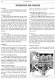
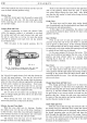
Fig.
6.
Driving out the first motion shaft with the aid
of
a soft metal drift.
gearbox, to clear the first motion shaft gear. Using
a long drift, inserted through the third motion shaft
opening, drive the first motion shaft forward, complete
with bearing and circlip, from the gearbox.
The laygears may now be removed from the gear-
box.
To remove the bearing from the shaft, knock
back the tab locking washer and unscrew the shaft
nut. This nut has a left-hand thread. The bearing can
now be driven from the shaft, preferably by resting the
circlip
of
the outer race on the jaws
of
an open vice and
driving the shaft downward.
Use a hide or lead hammer for the operation,
as
great care must be exercised to prevent the end of
the motion shaft from 'spreading'.