
Owners Manual


F/8
GEARBOX
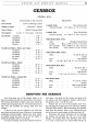
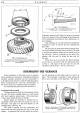
Fig. 8. Synchronising cone.
A. Chamfer to be machined after cone is shrunk into
position.
B.
Cone. C. Coupling adaptor.
D.
Con-
stant mesh gear.
c
HIO. 95. C.
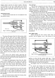
Fig. 9. Cone dimensions.
A.
Cone angle
5°
10'. B. Coarse thread turned with
.015-in. lead. C. Cone diameter 2. 5-in.
Fahrenheit, expansion will allow the cone to be pressed
home on to the gear without damaging the broaching and
will be sufficiently close fitting
to
resist displacement in
gear changing.
After shrinking on, the unit should be immediately
quenched in water
to
prevent the heat softening the
gear itself.
On each gear the appropriate speed coupling adap-
tor must be fitted before the cone,
but
there is no need
to pre-heat this adaptor, which can be pressed home in
the cold state. There is a shoulder on one side
of
the
adaptor, and this must be facing the gear and not
the cone.
When the cone is in position, the final machining
can be done in accordance with the dimensions given
in Fig.
9.
The taper
of
the cone must be true and
concentric with the bore to
.001 in. (.0254 mm.).
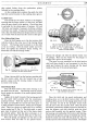
ASSEMBLING
THE
GEARBOX
Perfect cleanliness
of
the gearbox parts is essential
before assembly can commence. Although the following
complete assembly operation has been sub-divided,
it
is
advisable for the operator to read the whole description
before commencing any
work-the
sub-assemblies
of
the various parts are
so
interlaced with one another.
To reassemble the gearbox proceed
as
follows:-
Synchromesh
Sub-Assembly
During manufacture
both
the 1st speed gear and the
3rd and 4th speed coupling sleeves are each paired
with their respective synchronisers.
Only mated pairs
of
these parts should therefore be refitted.
Special guides are available to facilitate the re-
assembling
of
the three balls and springs into the syn-
chronisers. The guide is
of
the same diameter
as
the
coupling sleeve.
(See Fig. 10.)
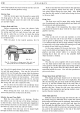
The guide is slipped over the synchroniser and
turned until the hole coincides with one
of
the three
sockets. A spring and ball are then placed in position,
the ball depressed and the guide rotated to hold
it
in
place. This procedure is repeated for each spring and
ball in turn until they are all depressed. The guide is
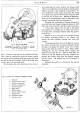
Fig. 10. Using Service
Tooll8G
40
to
assemble the
spring loaded balls to a coupling sleeve and syn-
chroniser.