
Owners Manual


GEARBOX
F/9
then pushed further along the synchroniser splines,
followed by the coupling sleeve.
As
the coupling sleeve replaces the guide, the balls
find their correct location in the coupling sleeve groove.
Layshaft Gears
First locate the two thrust washers to the laygears,
ensuring that the larger washer is at the front, and then
place the gear cluster in the gearbox. Check
that
there
is
end play for the cluster gears
of
between .001 and
.
003
inch, and remedy
if
necessary by fitting a thicker
or thinner rear washer. Temporarily replace the layshaft
with a thin
rod
which will permit the gear cluster to remain
out
of
mesh with the third and first motion shaft gears.
First Motion Shaft Gears
Press the ball bearing
on
to the first motion shaft
with the circlip
in
the outer race
of
the bearing facing
forward. The bearing must be pressed on to the shaft
as
far
as
it
will
go.
Refit the keyed washer and screw
down and tighten the left-hand thread locking nut.
Secure the
nut
with the locking washer.
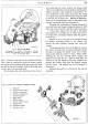
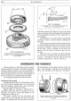
Fig. 11. Using Service
Tool
18G4
to assemble the
bearing
to
the first motion shaft.
Using a bronze drift, tap the bearing, complete with
the first motion shaft, into the forward face
of
the
gearbox casing until the bearing circlip
is
flush with
its recess in the casing.
Third Motion Shaft
Press the third motion shaft centre bearing
on
to
the shaft from the rear. The bearing must be pressed
firmly against the shoulder
of
the centre splined portion
of
the shaft.
Lightly oil the shaft forward
of
the bearing and refit
the first speed wheel assembly with the synchroniser
pointing forward. Refit the keyed thrust washer
on
the shaft and assemble the second and third gears on
to their phosphor bronze sleeves, which must be lightly
oiled. These two sleeves are made solid by a common
thrust washer (see
22,
Fig.
7).
The third speed, or small
gear, must be placed on
that
end
of
the sleeve which
has internal splines. Slide the sleeve and gears on to
the third motion shaft with the third gear to the front.
Place the spring and plunger into the hole in the
third motion shaft and slide on the splined washer.
E
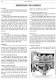
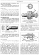
Fig. 12. Securing the third motion shaft gears.
A. Hole in shaft for locking peg.
B.
Spring. C.
Locking peg.
D.
Locking washer. E. Locking
washer with peg engaged.
Depress the plunger and slide the splined washer over
the plunger. Then turn the washer for the plunger to
engage with a groove
in
the washer.
The gears are now assembled on the third motion
shaft and there should be end movement for the first
speed gear between the centre bearing and the keyed
washer
at
the rear
of
the second speed gear.
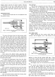
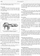
Fig. 13. Fitting the laygears into position with the
aid
of
Service Tool
lSG
6.
Place the third and top speed synchroniser and
coupling sleeve
on
to the third motion shaft, with the
coupling sleeve groove for the change speed fork to the
rear, and then oil and fit the phosphor bronze bush
into the end
of
the first motion shaft. Slide the third
and fourth synchronisers slightly forward on the shaft to
clear the laygears, and then carefully guide the third
motion shaft assembly into the gearbox casing. When
the housing, surrounding the third motion shaft bearing,
is
flush with the gearbox casing, the layshaft gear cluster
should be raised into mesh with the gears (see Fig.
13)
and the lays haft oiled and fitted into position. The lipped