
Owners Manual


GEARBOX
Fjll
THE
GEAR CHANGE MECHANISM
Descrjption
The gear change lever situated on the steering
column operates both a cable and mechanical linkage.
By
depressing or lifting the change lever the cable is
either pulled or pushed, and thus turns the selector
gate in the gearbox to select the desired gear.
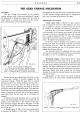
Fig. 15. The gear change and oiling points.
A.
"C"
lever pivot. B.
D.
E and J. Ball
joint
connec-
tions. C
and
F.
Cross shaft bearings. G. Gearbox
filler.
H.
Hand
brake pivot. K. Selector return spring.
By
moving the gear change lever forward, or rear-
ward the gear selected is actually engaged via the
mechanical linkage. When the gear lever is moved
forward, the lever arm rotates clockwise moving with
it
the
"C"
lever
at
its base. The
"C"
lever, in its turn,
forces downward the adjusting rod which in the same
movement rotates the linkage cross shaft. Thus the inner
arm
of
the cross shaft pulls upwards the connecting rod,
which is attached
at
its lever end to the main gearbox
cross shaft lever.
In
this way, 1st
or
3rd gears are
engaged.
If
the lever is moved rearward,
that
is toward the
driver, the whole linkage movement is reversed and the
gearbox cross shaft lever is also moved
to
the rear.
This movement engages the 2nd or 4th gears, or
if
the
knob
of
the change lever
ha:s
first been pulled outwards,
the reverse gear.
A biasing spring K, Fig.
15
has been incorporated
to facilitate the location
of
third gear.
That
is, when
disengaging second gear the spring ensures that the lever
is pulled upward through neutral ready to engage third
gear, thus obviating the crashing
of
first'gear.
Adjusting the Gear Controls
Change Speed Cable: Difficulty in gear selection
may be caused by the inner cable slipping in the
trun-
nion at either the steering or gearbox end, and should
be remedied by adopting the following
procedure:-
Assuming that inner cable movement
is
occurring
in the trunnion
at
the steering end, slacken off the
nut
securing the trunnion clamping bolt and, with the gear
lever in neutral, slightly lift the
"C"
lever and push the
inner cable downwards towards the gearbox to its fullest
extent. Re-tighten the clamping bolt nut.
If
the inner cable is slipping in the trunnion
at
the
gearbox end, place the gear lever in neutral and release
the clamping bolt nut.
Push the selector lever to its
fullest extent towards the rear
of
the gearbox and re-
tighten the clamping bolt nut.
The procedure given for adjusting the inner cable
at the gearbox end applies equally
well
when reconnecting
the cable to a new or reconditioned gearbox.
Mechanical Linkage: Fitted between the
"C"
lever
and the mechanism's cross shaft
ann
is
an adjustment
rod. When wear occurs in the linkage, the slackness may
be taken up by releasing the locknut
at
each end
of
the
adjuster, and then rotating the rod by its central
hexa-
gon. One end
of
the rod has a left-hand thread, the other a
right-hand thread, thus when rotated the rod either
shortens or extends the distance between the cross shaft
and the
"C"
lever.
Adjustments
of
this nature are rarely required,
probably only in the event
of
the complete dismantling
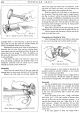
Fig. 16.
Showing a cutaway view
of
the gear change lever
head.