
Owners Manual


AUSTIN
A40
SERVICE
MANUAL
Gf
I
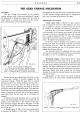
PROPELLER SHAFT
2
Fig.
I.
Exploded
view
of the front end universal joint.
I. Internal splined end
of
propeller shaft.
2.
Dust
cover.
3.
Front
half coupling.
4.
Spider.
5.
Oil nipple.
6.
Needle bearing assembly.
7.
Spring ring.
Description
The Propeller Shaft and Universal Joints are
of
Hardy Spicer manufacture (Fig.
1).
The fore and aft movement
of
the rear axle
and
other
components is allowed for by a sliding spline between
the propeller shaft
and
gearbox. Each universal joint
consists
of
a centre spider, four needle roller bearings
and two yokes. Reference
to
the Lubrication Chart in
Section T shows the location
of
the joints.
Lubrication
An
oil nipple
is
fitted to each centre spider for the
H70. 140, A.
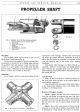
Fig.
2.
Showing the oil channels in a joint spider.
4
lubrication
of
the bearings. Grease must
not
be used
oil being the correct lubricant. Reference to Fig. 2
shows that the central oil chamber is connected to the
four oil reservoirs and to the needle roller bearing
assemblies.
The needle roller bearings are filled with oil on
assembly. Gearbox oil lubricates the sliding splined
joint between the propeller shaft
and
the gearbox.
Before refitting the propeller shaft to the gearbox, smear
the splines with oil.
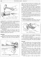
Tests for Wear
Wear
on
the thrust faces is located by testing the
lift in the joint, either by hand,
or
by using a length
of
wood suitably supported.
Any circumferential movement
of
the shaft relative
to the flange yokes, indicates wear
in
the needle roller
bearings,
or
the sliding spline.
Removal of Complete Assembly
Saloon : Release the rear end
of
the propel_ler shaft
from the axle flange by undoing four nuts and bolts
together with their lock washers. Before extracting the
propeller shaft from the gearbox, place a tray beneath
the rear end
of
the unit to catch surplus oil that may
drain
off.
Sports: Due to the large amount
of
frame boxing
necessary to provide chassis stiffness, the propeller shaft
is
embraced by a long tunnel. To remove
or
refit the