
Owners Manual


FRONT
HUBS
AND
INDEPENDENT
SUSPENSION
H/5
lower wishbone arms.
Fit
two short bolts into the vacant
holes and secure with the nuts. Remove the slave bolts
and fit the remaining two short bolts.
See
that all nuts
are securely tightened.
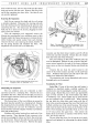
Removing the Suspension
Jack the car, remove the wheel and the coil spring
as
already explained. Disconnect the steering side-tube
from the steering arm by withdrawing the split pin and
unscrewing the nut. Also disconnect the flexible brake
fluid pipe
at
its union on the chassis, plugging the main
pipe
to
save loss
of
fluid.
With the suspension unit supported, remove the
fulcrum pins securing the lower wishbone arms
to
their
brackets under the frame, taking care to retrieve the two
rubber bushes and special washer from each bearing.
Unscrew the four nuts securing the shock absorber to
the top spring bracket and withdraw the bolts. The
suspension unit is now free to be lifted clear.
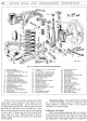
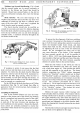
SJ.
149.
B.
Fig.
5.
The
inner rubber bushed bearings
of
the lower
wishbone arms are indicated at
A.
Dismantling the Suspension
The top wishbone arms are connected
at
their
narrowest point by a clamping bolt. Unscrew the nut
and
release this bolt. Next remove the split pin and nut
from the upper trunnion fulcrum pin on the outer end
of
the top wishbone arms.
The forward arm
of
the top wishbone is secured to
the shock absorber spindle by a clamping bolt. Slacken
the clamping bolt and partially withdraw the arm. The
trunnion fulcrum
pin
can now be withdrawn and the
shock absorber removed complete with the top wishbone
arms and packing piece.
Withdraw the rubber bearing from each end
of
the
upper trunnion. These bearings fit into a groove in the
swivel pin and must be taken out before the swivel pin
can be removed. Remove the split pin and unscrew the
nut from the top
of
the swivel pin. Remove the upper
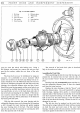
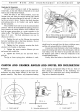
Fig. 6. This exploded view shows the assembly
of
the
screwed bush bearing
at
the outer end
of
the lower
wishbone arms.
trunnion and the three thrust washers and lift off the
swivel axle and hub assembly. Detach the cork washer
from the lower end
of
the swivel pin.
The outer bearing
of
the lower wishbone arms can
now be dismantled. Slacken the nut on each
of
the half-
moon cotters located in the ends
of
the lower wishbone
arms, screw out the two threaded bushes and detach the
arms.
Unscrew the nut from the cotter located in the
centre
of
the lower trunnion and tap out the cycle-type
cotter. Withdraw the fulcrum pin and remove the cork
washer from each end
of
the trunnion.
The suspension unit
is
now dismantled, and worn or
damaged parts can be renewed.
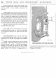
Examination for Wear
Swivel Pin:
If
wear
of
the swivel pin and bushes is
suspected
as
described earlier, carefully examine the
swivel pin for wear by checking for ovality with a micro-
meter gauge.
Should the pin not show any appreciable
signs
of
wear renewal
of
the swivel bushes may effect
a satisfactory cure. These bushes can be easily driven
out and replaced with a suitable drift. When refitting
the top bush the oiling hole must locate with the oil
hole in the swivel housing and the top
of
the bush must
be flush with the top
of
the swivel housing. The second
bush must be flush with the recess at the bottom
of
the
lower swivel housing and protrude about
l
of
an inch
(3.
175
mm.) above the upper face. Then reamer the
bushes from the bottom
as
necessary with Service Tools
Nos. 18G
64
and 18G
65.
The two piece dust cover for the swivel pin
is
easily
removed and replaced by telescoping the spring loaded
tubes.