
Owners Manual


H/6 F R 0 N T H U B S A N D I N D E P E N D E N T S U S P E N S I 0 N
Wishbone Arm Screwed
Bush
Bearing:
If
it
is
found
that the screwed bushes can be moved backwards or
forwards on the fulcrum pin thread they should be
renewed. Should new screwed bushes on the old ful-
crum pin still permit end play, then renew the fulcrum
pin.
Shock Absorber: The cross shaft bearings
of
the
double acting hydraulic shock absorber may have worn
sufficiently to permit up
and
down or sideways move-
ment
of
the cross shaft.
If
such wear
is
apparent the
shock absorber must be renewed complete.
The shock absorber should also be carefully
ex-
amined for any leaks and tested for effective damping.
Secure the shock absorber mounting plate in a vice and
move the top wishbone arms up and down through a
complete stroke. A moderate resistance throughout the
full stroke should be felt.
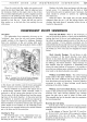
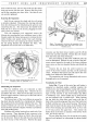
Fig.
7.
Showing the Girling front shock absorbers
and
top wishbone arms.
If
resistance
is
erratic
it
may mean that the fluid
level is too low and that there are air locks in the shock
absorber. To rectify this, the shock absorber filler plug
should be removed and the fluid level maintained to
just below the filler plug opening, while the lever is
moved steadily up and down through full strokes.
If
this treatment does
not
effect a cure the shock absorber
must be renewed
as
a complete unit.
On the A40 Sports the shock absorbers are
of
Girling
manufacture (See Fig.
7),
and
though they differ in
appearance from the Armstrong type, their principle
of
operation
is
similar.
Assembling the Suspension
First
fit
the screwed fulcrum pin into the lower
trunnion
at
the bottom end
of
the swivel pin, ensuring
that it is centralised and secured by means
of
the cycle-
type cotter.
Fit
a cork ring into the recess provided
at
each end
of
the lower trunnion and introduce the
lower wishbone arms into position. Ensure that the half-
moon cotters are correctly positioned to receive the
steel bushes which should now be greased and screwed
partly home.
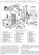
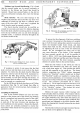
Fig. 8. Illustrating the suspension assembly fixture.
Service
ToollSG
89.
To ensure that the alignment
of
the lower wishbone
arm is correct, it is necessary, in the absence
of
a suitable
jig, to bolt the lower spring plate securely in position.
Screw the threaded bushes home evenly, and then
slacken them back one flat. Finally secure the bushes
by
tightening the nuts on each
of
the two half-moon
cotters.
Do
not overtighten the cotter nuts as this
may cause distortion
of
the bushes.
If
the assembly
has been correctly carried out it will be possible to
insert a .
002-in. (
.0503
mm.) feeler gauge between the
inner shoulder
of
the bush and the outer face
of
the wish-
bone arm on each side. The lower trunnion assembly
should now operate freely
in
the screwed bushes.
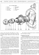
Place the cork washer on the swivel pin with its
chamfered face downward and smear the swivel pin
with a little clear engine oil. Then position the swivel
axle and hub assembly on the swivel pin. The thrust
washers, comprising one
"Oilite" washer interposed
between two
"Staybrite" washers should next be fitted.
The
"Staybrite" washers are supplied in varying thick-
nesses to permit adjustment,
as
it
is
necessary to provide
easy operation
of
the swivel axle with a minimum amount
of
lift. The maximum permissible lift is . 002-in.
(.
0508
mm.). Fit the upper trunnion and swivel nut, and
check the clearance correcting it
if
necessary by means
of
the "Staybrite" washers. Then slacken the swivel
pin nut to permit further assembly.
Moisten the upper trunnion rubber bearings with
water and place them in position. The trunnion with its
bearings should next be placed in position between the
two upper wishbone arms, after which the fulcrum pin
should be fitted and the slackened upper wishbone arm
repositioned and tightened to the shock absorber shaft.
Secure the clamping bolt located between the two shock
absorber arms.
Note that the swivel pin and upper trunnion fulcrum
pin nuts must
not
be tightened at this stage.