
Owners Manual
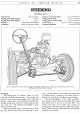


STEERING
J/3
Fig.
3.
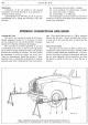
The toe-in must be adjusted so
that
A is
T.r
to
t inch less
than
B.
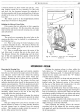
To remove the tubes, withdraw the split pin and
release the
nut
at
each end
of
the tube
and
then carefully
tap the tubes clear
of
the levers to which they are at-
tached. When removing one
of
the connections from
either end
of
the steering gear double lever, always
support the lever
to
prevent any shock from being
transmitted to the steering gear where damage may be
caused.
Tube Connections
Some steering side and cross-tubes are equipped with
the Austin patent ball and socket connections which are
screwed into the ends
of
the tubes
and
can be adjusted
to take up wear. These connections consist
of
a threaded
and castellated lower socket screwed into position and
locked by a split-pin. The body
of
the tube-end has
four split pin holes drilled, vernier-pattern,
at
a different
pitch from
the
castellations in the socket, thus permitting
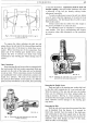
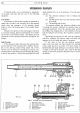
Fig.
'~·
Illustrating the self-adjusting type ball
and
socket connection.
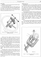
a very fine adjustment. Adjustments should
be
made and
checked regularly, otherwise undue slackness will cause
a deformity
of
the ball pin thereby making further
adjustment impossible.
To make
an
adjustment, remove the split pin, lightly
screw it back to the first alignment
of
the split pin hole
and castellation. The ball should then be able to move
freely in the socket.
Always ensure
that
the rubber
boot
fits snugly in
the groove provided for it
in
the tube end.
An
alternative type
of
connection is employed
on
some models. This type is self-adjusting and requires
no attention other than lubrication
at
the prescribed
intervals.
Fig. 5. Showing the adjustable type
of
the. Austin
patented ball
and
socket connection.
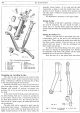
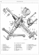
Removing the Double Levers
These are held to the steering gear rocker shaft and
to the idler shaft respectively by a
nut
and
split pin.
With the removal
of
the
nut
and split pin, the double
levers can be withdrawn from their splined shafts by
using
an
extractor. See Fig.
11.
Never attempt to lever
or hammer the steering gear double lever from the rocker
shaft, otherwise serious damage to the steering gear
may result.
Removing the Idler
With the side and cross-tubes disconnected the idler
can be detached from the chassis.
It
is secured by
three bolts, inserted from the inside
of
the dumb-iron
and
terminating in the three tapped holes
in
the idler
flange. Support the idler with the hand and unscrew the
setscrews until their threads are clear
of
the holes,
when the idler can be detached.