
Owners Manual


J4
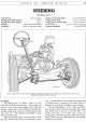
STEERING
~~--=
..
=
....•
~·.·.·
..
·.
'\_~
-q '
)~
H40. 169.
A.
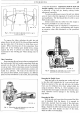
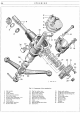
Fig. 6. Steering idler parts exploded
I.
Cap
setpin and washer.
8.
Washer.
2.
Idler cap. 9.
Double
lever.
3.
Oil plug. 10. Slotted
nut
and
pin.
4.
Joint
washer.
II.
Washer.
5.
Idler body.
12.
Lower bush bearing.
6.
Idler shaft.
13.
Upper bush bearing.
7.
Cork seal.
Dismantling and Assembling the Idler
The idler
top
cap
is
secured to the body by three
setpins
and
has a
joint
washer inserted between cap
and
body. Lubrication
is
effected
by
removing the oil plug
in
the cap
and
injecting oil
into
the body.
Internally 'the
body'
has a recess
in
the
head
and a
plain bore right through. Two
phosphor
bronze bush
bearings, with internal oil grooves, are pressed into
position, one
at
the
top
and
the other
at
the
bottom
of
the body.
At
the lower end
of
the
body
a cork seal butts
up
to
the lower bearing
bush
and
is
retained
in
position
by
a steel washer, which
in
turn,
is
secured
by
the bore
of
the body being
"peened"
over. By removing this burr,
with the aid
of
a
hand
scraper, the washer
and
cork seal
can be extracted.
The idler shaft can be removed
by
hand
once the
body cap has been released. The flange
of
the idler shaft
locates in the recess within
the
body head
and
the two
highly finished portions
of
the shaft rotate within the
phosphor bronze bushes.
At
its lower end the shaft
incorporates a spline to
take
the double lever
and
a
portion
of
screw thread
to
take the lever securing nut.
The idler shaft is drilled for passing lubrication
to
the
bearing bushes.
No
adjustment
is
necessary for this type
of
idler.
Refitting the Idler
The
refitting
of
the idler is generally a reversal
of
the removal procedure,
but
care should be
taken
to
ensure
that
it
is
secured firmly against the frame by
means
of
the three bolts with spring washers beneath their
heads.
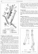
Refitting the Double Levers
There is a location
mark
in
the double lever
and
a
corresponding
mark
on
the
end
of
the
steering gear
rocker shaft. When refitting the double lever
make
sure
that
these marks coincide. Press the lever
on
to
the
splined shaft
and
secure it with the castellated nut,
plain washer and split pin.
To
check for the correct fitting
of
the lever, ensure
that
there is a distance
of
approximately 3-ins. between
the underside
of
the frame side member
and
the
upper
machined face
of
the rear
arm
of
the lever.
Press the lever
on
to the splined shaft and secure
H40. 76.
B.
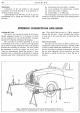
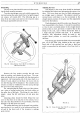
Fig. 7. Checking the alignment
of
a swivel
arm
(method 2).