
Owners Manual
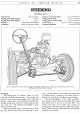


STEERING
Jj5
it with the slotted nut, plain washer and split pin. Note
that location marks are
not
necessary for this lever
and
shaft,
but
the clearance between the underside
of
the frame member
and
the rear machined face
of
the lever
should be the same as for the lever fitted to the steering
box shaft.
The wheels must be in the straight-ahead position
while these two levers are being fitted.
Refitting the Side and Cross-Tubes
First connect the two side-tubes to their respective
steering arms
and
levers.
Fit
the cross-tube
and
ensure
that both the side
and
cross-tube securing nuts are tight
and
split pinned.
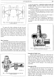
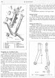
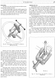
Swivel Arms
The swivel arms connecting the swivel axles to the
steering side-tubes may be checked for misalignment
in
the following
way:-
(1)
Place a rule along the brake backplate so that
it projects alongside the arm. The distance between the
centre
of
the ball pin locating hole and the rule should
be !-in. plus
or
minus [
6
-in.
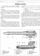
(2)
Place a straight-edge across the centre
of
the
bolt holes used to secure the arm to the swivel axle.
The distance between the straight-edge
and
the lower
face
of
the arm machined face against which the ball
pin
nut
fits-should
be
~~-in.
plus or minus [
6
-in. (See
Fig .7.)
Fig. 8. Checking a swivel arm for misalignment
(method 1).
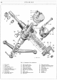
STEERING GEAR
Removing the Steering Gear
To remove the steering gear and column complete
from the car, first remove the upper portion
of
the direc-
tion indicator control tube from within the steering
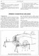
column. Release the three grub screws which pass
through the steering hub
to
secure the
horn
quadrant.
At the steering box end
of
the column, the horn and
indicator electrical cables should be disconnected
at
the
nearest snap connections. The horn quadrant and short
stator tube may then be withdrawn complete with cables.
It
will be noticed
that
the
short tube has a number
of
indentations
on
its outer diameter, thus forming lugs
internally, which locate
in
the slot
of
the long tube
remaining within the steering column.
Finally remove the locknut retaining the steering
wheel in position. With a sharp jerk upwards the wheel
may be freed from the splines and so removed from the
column.
The gear change lever
and
rod
are secured to the
steering column by means
of
a clamp bracket, therefore·
the gear change must be released from the steering
column. This operation simply entails the removal
of
the two Allen screws from the bracket.
Holding the steering column
in
place within the
body there is a
"U"
bracket which
is
secured to the
underside
of
the fascia panel. To dismantle this bracket,
release the two setpins
and
remove the
"U"
bracket
complete with its packing.
Next jack up the car at its front end and remove the
bumper and apron, two operations
that
have been
detailed under the Bodywork section
of
this manual.
(In the case
of
the Sports and Commercials,
it
is only
necessary to remove the front number plate.)
Remove the double lever from the rocker shaft, as
previously described. Finally disengage the steering box
from its mounting
by
removing the single
nut
and bolt
and
relative washers,
and
the two rear setpins
and
spring
washers, all
of
which pass through the chassis side mem-
bers, to the steering supporting bracket.
The steering gear complete with column may now be
withdrawn from the car by
an
outward movement
and
a
slight twisting to avoid the bodywork.
When replacing the steering, reverse the removal
procedure
but
do
not
tighten the box securing setpins
and
single bolt, until the column has been secured within
the driving position.