
Owners Manual


AUSTIN
A40
SERVICE
MANUAL
K/1
REAR
AXLE
GENERAL DATA
Type
! floating
Pinion Front (cont.):
Oil Capacity
2t
pints; 2. 7 U.S. pints
Type
Taper Roller
1.
28
litres Size
1
x2tx!x
1~-in.
Final Drive
Spiral Bevel
(25.4x63.8x
15.8x20.6
mm.)
Crown Wheel Teeth: Saloon
..
37
Pinion Rear:
Sports
36
Make
... Timken or Skefko
Commercials ...
43
Type
Taper Roller
Bevel
Pinion Teeth 7
Size
1.25 X 2.
8593
XO.
9375
X 1.1811-in.
Ratio: Saloon
5.28:1
(31.
75
X 72.62 X 23.81 X 29.
99)
Sports
5.14:1
Differential:
Commercials ...
6.14:1
Make
R.
and M. LJT
40
(3
DOT)
Crown Wheel to Pinion Backlash .
005-. 008-in.
Type
Double Purpose Ball Journal (light)
(.127-.2032 mm.)
Size
40x80xl8
mm.
Hub:
BEARINGS
Make
R.
and M.
LDJ
40
Pinion Front:
Type
Ball Journal Double Row (light)
Make
Timken or Skefko Size
40x80x23
mm.
MAINTENANCE
Axle
Shaft--To Remove and Replace
Chock all wheels
not
being operated upon.
Jack up the car and lower the spring on to blocks
as
close
as
possible to the axle.
Remove the wheel.
Take out the drum locating screw, using a screw-
driver. The drum can be tapped off the hub and brake
linings, provided the handbrake is released and the brake
shoes are
not
adjusted so closely
as
to bind on to the
drum.
Should the brake linings hold the drum when the
handbrake
is
released,
it
will be necessary to slacken the
brake shoe adjuster a
few
notches.
Remove the axle (differential) shaft retaining screw
and
draw out the axle shaft by gripping the flange out-
side the hub.
It
should slide easily, but
if
it
is tight on
the studs,
it
may need gently prising with a screwdriver
inserted between the flange and the hub. Should the
paper washer be damaged
it
must be renewed when
reassembling.
Replacement is a reversal
of
the above operation.
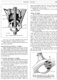
Hubs-
To Withdraw and Replace
Remove the wheel and axle shaft
as
described, when
the hub retaining
nut
will be accessible. This nut is
locked in position by a keyed washer which is hammered
down on to one
of
the fiats
of
the nut. Knock back
the washer and remove the
nut
with a well-fitting
spanner such
as
Service Tool No. 18G
23.
The lockwasher can be removed by hand tilting
it
so
that the key disengages with the slot in the threaded
portion
of
the axle case.
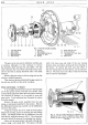
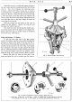
To use the extractor
GT.lO on the rear hub the
adapter will
be
needed.
It
will be seen that the adapter
fits
into the end
of
the axle tube and provides a stop for
the extractor bolt.
The extractor is fitted over the wheel studs
and
held
in position by two wheel nuts screwed well down.
By
screwing up the central bolt
of
the extractor, using
either a spanner or a tommy bar, the hub and double-
row ball-bearing, together with washers and oil seal,
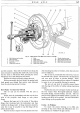
will be withdrawn. Fig. 3 shows the assembly order.
The bearing can be tapped out
of
the hub with the
aid
of
a drift.
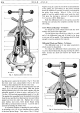
To Reassemble
The hub bearing is
not
adjustable and is replaced
in one operation.
It
is essential that the face
of
the outer race pro-
trudes .
001-. 004-in. (. 0254-.
1016
mm.) beyond the face
of
the hub plus paper washer when the bearing
is
pressed
into place. This ensures that the bearing
is
definitely
gripped between the abutment shoulder in the hub and
the flange
of
the differential shaft.
The hub is then mounted on the axle tube, followed
by the lockwasher (which has a tongue to register with
the groove or hole) and finally the securing nut.
Tighten up the nut until the hub is fully home, and
then secure by tapping down the lockwasher on one of
the fiats
of
the nut.
Replace the axle shaft, carefully finding the spline
engagement with the differential unit and ensuring that
the flange and washer are threaded over the hub studs
in the position in which the ten small holes
of
the flange