
Owners Manual


K/4
REAR
AXLE
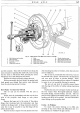
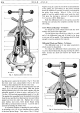
Fig.
3.
Rear hub assembly exploded,
I.
Axle shaft flange.
6.
Oil seal.
11.
Shock absorber arm.
2.
Joint washer.
7.
Hub
casing.
12. Arm securing nut.
3.
Hub
locknut.
8.
Back plate securing nut.
13.
Lockwasher for back plate
securing nut.
4.
Hub
lockwasher.
9.
Spring
"U"
bolt.
5.
Hub
bearing.
10.
Spring.
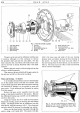
The
gear carrier unit
can
be withdrawn with the axle
in position, although
it
is first necessary
to
remove
the propeller shaft
and
then
the axle shafts.
For
this
latter operation the
road
wheels
and
brake drums
must
also be removed as already described under 'Axle shaft
removal'.
Remove the gear carrier
unit
drain plug
and
run
the
oil into a suitable receptacle.
Then remove the nuts which hold the gear carrier
to
the axle case
and
lift
out
the carrier complete.
Pinion and
Bearings-
To Remove
It
is strongly advocated
that
operators should make
use
of
the
special service tools
that
are available This
is
particularly
important
where the bevel pinion bearings
are concerned
if
damage is
to
be avoided to races
and
gear carrier. Tools mentioned are illustrated in section
Q
of
this manual.
Remove
the
gear carrier assembly from the axle
casing, as previously described in this section. Remove
the differential bearing caps
and
lift
out
the differential
unit from the carrier.
Using
the
wrench 18G 34
to
hold the bevel pinion
flange from turning, remove its securing
nut
and
locking
washer. The flange should now be withdrawn from
the
bevel pinion, using
the
extractor 18G 12.
The
oil seal and
end cover should be removed by releasing four setpins.
Drive
out
the bevel pinion rearwards through the
carrier, using a soft metal drift. The pinion will
take
14.
Wheel stud.
with
it
the inner race
and
roller
of
the rear bearing
distance piece
and
shims, leaving the front bearing in
the carrier.
To
remove
the
inner race
and
rollers
of
the
rear bearing from
the
bevel pinion, use the extractor
18G
12.
The
inner race
and
rollers
of
the
front bearing
can be removed with fingers.
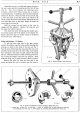
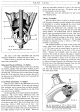
Fig.
4.
The taper roller bearings are subjected to a
pre-load
of
5
to
7 in.-lbs. controlled by shims fitted
between the pinion sleeve
and
the inner races
of
the
bearings.