
Owners Manual


AUSTIN
A40
SERVICE
MANUAL
Mjl
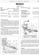
BR.AI{ES
GENERAL DATA
Make
Type Hydraulic,
Girling
Two-leading shoe front
...
i-in.
(3
.175 mm.)
... Pistol Grip Type
Mechanical on Rear Wheels only
Pedal Free Movement ...
Handbrake
Total Braking Area. (Saloon)
(Sports)
Inside Drum Diameter. (Saloon)
(Sports)
Principle of the System
83
sq. in. (535. 5 cm.
2
)
129
sq. in. (832.2 cm.
2
)
9-in. (22.
86
em.)
10-in. (25. 4 em.)
The hydraulic system consists
of
a supply
tank
which should be maintained
at
its correct level with
genuine Girling Crimson Brake Fluid, a master cylinder
in which fluid pressure is generated, wheel cylinders which
transmit fluid
to
the brake shoes,
and
a pipe line con-
sisting
of
tubing, hoses
and
unions connected
to
the
cylinders.
The application
of
the foot pedal operates a piston
in the master cylinder, applies pressure
to
the fluid in
the system, which causes
the
wheel cylinder pistons
to
expand the brake shoes.
When all the brake shoes are in contact with the
drums, solid resistance
is
obtained
at
the pedal.
Further
effort
at
the
pedal generates high pressure
in
the master
cylinder
and
throughout the system, therefore increasing
the force applied to the
brake
shoes.
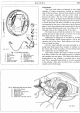
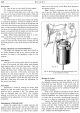
Fig.
1.
Master cylinder and pedal layout (Saloon).
A.
Brake pedal oil nipple.
B.
Pedal adjuster. C.
Supply union. D. Compression union. E.
Stop
light switch. F. Clutch pedal oil nipple.
Shoe Lining Width. (Saloon)
(Sports)
Shoe Lining Length:
Front and Rear (Saloon)
Front (Sports)
Rear Leading Shoe (Sports)
Rear Trailing Shoe (Sports)
Shoe Lining Thickness :
Front and Rear
Ll-in. (31.
75
mm.)
1£-in. (44.45 mm.)
8. 3-in. (21.
08
em.)
9. 44-in. (23.
97
em.)
9.
44-in.
(23
.
97
em.)
8. 56-in. (21.
74
em.)
...
k-in.
(4.
76
mm.)
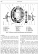
Fig.
2.
Master cylinder and pedal layout (Sports).
A. Brake pedal oil nipple.
B.
Stop light switch.
C. Supply union.
D.
Compression union.
E. Clutch pedal oil nipple.
F.
Brake pedal adjuster.
The pressure generated
in
the
master cylinder is
transmitted with equal
and
undiminished force
to
each
wheel cylinder, thus producing perfect equalisation and
efficiency in direct
proportion
to the effort applied
at
the
pedal.
When
the pedal is released, the brake shoe return
springs force the wheel cylinder piston,
and
therefore
the fluid, back to
the
original position in the system.
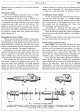
Handbrake
This control is situated beneath the fascia, close to the
steering column,
and
operates mechanically on the rear
wheels only. Adjustment must be made
at
the point
where
the
handbrake
rod
is attached to
the
handbrake
lever (see Fig. 3),
but
on
no
account should
an
attempt be
made
to
take up play by adjusting the handbrake cable.