
Owners Manual


M/4
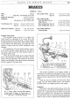
BRAKES
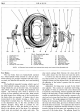
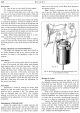
Fig.
6.
Rear brake back plate.
1.
Adjustment unit.
9.
Bleed valve ball.
17.
Seal spring.
2.
Back plate.
10.
Bleed screw.
18.
Seal support.
3.
Shoe and lining.
11.
Expander tappet.
19.
Return spring.
4.
Hydraulic cylinder.
12.
Setscrew.
20.
Shoe and lining.
5.
Rubber seal.
6.
Piston.
13.
Cover plate.
14.
Tappet roller.
21.
Adjustment wedge.
22.
Operating link.
7.
Dust
Cover.
15.
Roller wedge.
23.
Adjustment housing.
8.
Housing
nut
and washer.
16.
Cylinder housing.
24.
Setpin and washer.
NOTE: As illustrated some models have indented shoe steady rests instead
of
the adjustable kind.
Rear Brakes
The rear brake shoes are hydraulically operated
by
a wheel cylinder which consists
of
a die cast alum-
inium housing, two plungers complete with dust covers,
two seals, two bakelite seal retainers, and a seal retaining
spring.
The handbrake expander housing, which
is
part
of
the wheel cylinder casting, consists
of
a hardened steel
wedge which also acts
as
the draw link, two hardened
steel rollers and two flat inclined faced hardened steel
tappets. The retaining cover, which
is
secured to the
housing by four setscrews, has two tabs; these prevent
the plate tappets from sliding out
of
the housing when
the brake shoes are removed. A bleeder valve is also
incorporated
in
the cylinder housing, a rubber cover
being fitted to exclude dust, etc. The shoes are located
at the adjustment end, in the slots provided in the
adjuster plungers, being held in position by two
springs from shoe to shoe, the shorter
of
the two
is
fitted at the adjuster end
of
the shoes. Two adjustable
steady rests are provided, one under each shoe. The
shoe return springs fitted between the shoes and the
back plate ensure that the shoes rest upon the posts.
It
will be seen that the shoes are not anchored in
any
fixed
position but are allowed to slide both at the
hydraulic pistons and the adjuster links.
By
this method
the efficiency
of
the brakes
is
greater than the normal
fixed
pivot type.
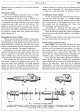
Adjustment for lining wear is made by the brake
shoe adjuster. This consists
of
a hardened steel wedge,
the spindle
of
which
is
screwed with a fine thread and
is
carried in a steel bearing, which is spigoted and bolted
firmly to the back plate.
On the outside end
of
the wedge
spindle are machined flats, which enable a spanner to be
used, and on its inner face four flats (of a predetermined
depth) are cut. The wedge engages two links, also with a
bearing in the housing, which have inclined faces.
On
the outer end
of
these links, grooves are formed in which
the brake shoes are located.
For
adjustment the rotation
of
the wedge in a clockwise direction causes
it
to move
inwards, forcing the links apart and expanding the ful-
crum end
of
the brake shoes. The adjuster should
be