
Owners Manual
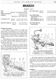


BRAKES
M/5
tightened up until a resistance is felt and then slackened
back two clicks.
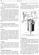
The Master Cylinder
This is the Girling compression type
of
cylinder
and
it
is fixed to the chassis frame by two bolts.
The assembly as shown in Fig. 7 consists
of
a
cast-iron housing with a highly finished bore into which
is assembled the plunger, complete with return spring,
recuperating seal, outer seal and seal retainer. The
plunger is operated by means
of
a push rod, with har-
dened ball end, locating in a specially formed hardened
steel seating. The whole is protected from dirt and dust
by
means
of
a rubber dust cover, packed with Girling
Rubber Grease No.
3.
Dismantling the Master Cylinder
Before removing the master cylinder for dismantling
it
is advisable to drain off most
of
the brake fluid by
disconnecting one
of
the flexible brake pipes on the front
wheel back plates, lowering the open end into a clean
container and pumping the brake pedal until no further
fluid enters the container. Re-connect flexible hose.
Disconnect the two pipe unions on the top
of
the
cylinder and disconnect the master cylinder piston
rod
from its connection
at
the brake pedal link rod. The
master cylinder may now be removed once the two
securing screws to the chassis frame have been withdrawn.
First unscrew the end cover and remove complete
with gasket, withdraw the plunger return spring.
Re-
move the rubber boot, withdraw the circlip retaining
washer
and
push rod. The plunger complete with seal
retainer and end seal is
pushed from the pressure end
of
the cylinder. Remove the recuperating seal from the body.
17
7
Carefully examine the various parts and renew any that
appear worn or damaged.
It
is particularly important
to renew any
of
the seals which are perished or worn.
Assembling the Master Cylinder
Fit the recuperating seal with lips facing the
pres-
sure end and make sure
that
it
is correctly seated.
Assemble the end seal and seal retainer, with the wider
end.
of
the seal next
to
the plunger and mount
it
into
the cylinder from the recuperating end. Smear the
seal and plunger with clean brake fluid.
Reassemble the operating rod and circlip, and
replace the plunger return spring, end cap and gasket.
Screw the end cover firmly into position and replace
the rubber boot on the cylinder, packing
it
with Rubber
Grease No.
3.
Refit the master cylinder to the chassis and connect
up the two pipe unions and the piston rod.
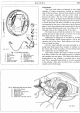
Fitting of Replacement Brake Shoes
Front Brakes: To remove the old shoes first jack
up the car and remove
road
wheels and drums. Lift
one shoe out
of
its abutment slot and release.
It
will be
found quite simple to remove the return spring. The
same procedure can be used with the other shoe. To
prevent the two wheel cylinder pistons expanding
it
is
advisable
to
place a rubber band round the cylinders.
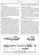
Clean down the back plate and
turn
the adjusters
back to the full off position. Assemble the replacement
shoes with the swan neck ends
of
the springs through the
holes in the back plate. Each shoe can be replaced
independently. The brake shoe steady rests, operating
and abutment ends
of
the shoes should be smeared with
Girling brake grease before assembly. Adjust the brakes.
9
II
14
~til~
I
.J~~~·
f
@J
I
I
10
13
I
2
3
4
8
RBJ~~
15
870.
132.
c.
12
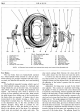
Fig,
7,
Components of the master cylinder,
1.
Locknut.
2.
Rubber boot.
3.
Circlip.
4.
Push rod.
5.
Collar.
6.
Retaining washer.
7.
Seal retainer.
8.
Seal.
9.
Plunger.
10.
Shim washer.
11.
Recuperating seal.
12.
Return spring.
13.
Gasket.
14.
End cover.
15.
Stop light switch.
16.
Master
cylinder body.
17.
Master cylinder complete.