
Owners Manual

0/10
Setting Temperature
10
deg.
C.
(50
deg. F)
20
deg.
C.
(68
deg. F)
30
deg.
C.
(86
deg. F)
40
deg.
C.
(104
deg. F.)
ELECTRICAL
Voltmeter Reading
16.1-16.7
15.8-16.4
15.6-16.2
15.3-15.9
If
the voltage at which the reading becomes steady
occurs outside these limits, the regulator must be
adjusted.
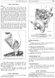
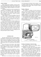
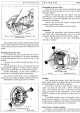
Shut off the engine, remove the control box cover,
release the locknut (A) Fig.
12
holding the adjusting
screw (B)
and
turn the screw
in
a clockwise direction to
raise the setting or
in
an
anti-clockwise direction to
lower the setting.
Turn
the adjustment screw a fraction
of
a
turn
and
then tighten the locknut.
When adjusting, do not
run
the engine up to more
than
half
throttle because, while the dynamo is on
open circuit,
it
will build
up
to a high voltage
if
run at a
high speed
and
in consequence a false voltmeter reading
would be obtained.
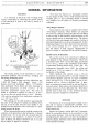
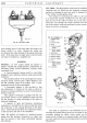
E ·018"
c
D
F
·006''-·017'~
MC. 35.
A.
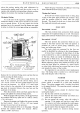
Fig. 13. Regulator mechanical setting.
A. Armature.
C.
Bobbin core.
E. Armature fixing screws.
Mechanical Setting
B.
Regulator frame.
D. Fixed contact.
F. Packing shims.
The mechanical setting
of
the regulator is accurately
adjusted before leaving the works, and provided the
armature carrying the moving contact is not removed,
the regulator will not require mechanical adjustment.
If, however, the armature has been removed from the
regulator for any reason,
the
contacts will have to be
reset. To do this proceed as
follows:-
EQUIPMENT
(a) Slacken the two armature fixing screws (E) Fig.
13.
Insert . 018-in. (. 4572 mm.) feeler gauge between
back
of
the armature
"A"
and
the regulator frame.
(b) Press back the armature against the regulator frame
and down
on
to the
top
of
the bobbin core with the
gauge in position, and lock the armature
by
tighten-
ing the two fixing screws.
(c)
Check the gap between the underside
of
the arm
and the top
of
the bobbin core, this should be
.012-.020-in. (.3048-.508 mm.).
lfthe
gap is out-
side these limits, correct them by adding
or
removing
shims (F)
at
the rear
of
the fixed contact.
(d) Remove the gauge
and
press the armature down,
when the gap between the contacts should be
.006-.017-in. (.1524-.4318 mm.).
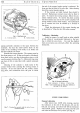
Cleaning the Contacts
To render the regulator contacts accessible for
cleaning, slacken the securing plate carrying the fixed
contact
in
order that the contact plate may be swung
outwards. Clean the contacts by means
of
a fine car-
borundum stone
or
fine
emery cloth. Carefully wipe
away all traces
of
dirt
or
other foreign matter before
finally tightening the securing screws.
Cut-Out Adjustment
Electrical Setting
If
the regulator setting is within the correct limit,
but
the battery is still
not
receiving current from the
generator, the cut-out may be
out
of
adjustment, or
there may be
an
open circuit
in
the wiring
of
the cut-out
and regulator unit.
Remove the cable from the terminal marked A
on
the
control box (ensuring
that
the bared end does
not
come
into contact with the chassis). Remove the voltmeter
lead from the D terminal
of
the
unit
and connect
it
to
terminal A.
Run
the engine as before;
at
a fairly low
engine speed, the cut-out should operate, when a volt-
meter reading should be given
of
the same value as
that
when the voltmeter was connected to terminal
D.
If
there is no reading, the setting
of
the cut-out
may be badly out
of
adjustment
and
the contacts
not
closing. To check the voltage
at
which the cut-out
operates, remove the control box cover, and connect
the voltmeter between the D terminal and earth. Start
the engine
and
slowly increase its speed until the cut-out
contacts are seen to close, noting the voltage
at
which
this occurs.
This should be 12.7-13.3 volts.
If
operation
of
the cut-out takes place outside
these limits,
it
will be necessary to adjust. To do this,
slacken the locknut
on
the cut-out adjustment screw and
turn the screw
in
a clockwise direction to raise the
voltage setting,
or
in an anti-clockwise direction to