
Owners Manual

0/14
ELECTRICAL
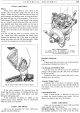
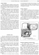
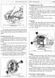
Fig. 19. The starter switch.
good earthing point.
If
the lamp lights, the cable to the
starter switch is in order. Operate the switch and
test between the other terminal
of
the starter switch and
earth.
If
the lamp does
not
light starter switch is faulty
and must be replaced
as
a complete unit.
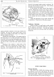
IGNITION
Distributor:
At
slow engine speeds the ignition is
slightly retarded, but
at
high speeds
it
is advanced
by
an
automatic timing control mechanism working under
centrifugal force.
A vacuum-operated timing control is also fitted,
designed to give additional advance under part-throttle
conditions.
The combined effects
of
the centrifugal and vacuum
operated timing controls gives added efficiency over
the full operating range
of
the engine, with a corre-
sponding economy in fuel consumption.
A micrometer adjuster is also provided so that
fine
adjustments to timing can be made to allow for
changes
in
running conditions, e.g. state
of
carbonisation,
change
of
fuel, etc.
The
capacitor connected in parallel with the con-
tact breaker points is
of
the metallised paper type and
has the property
of
being self-healing in the event
of
dielectric breakdown.
A measure of radio and television interference
suppression is provided by the carbon brush that forms
the connection to the rotating electrode
of
the distri-
butor. This brush has the effect
of
a suppression resistor
in the lead from the coil to the distributor.
Coil: The ignition coil requires no attention beyond
seeing
that
the terminal connections are tight, and
that the exterior is kept clean, particularly between
the terminals.
EQUIPMENT
H.T. Cables: The high tension cables must be carefully
examined, and any which have the insulation cracked,
perished or damaged in any way, must be replaced
by
7 mm. rubber covered ignition cable.
The method
of
connecting the cables to the coil
is to thread the knurled moulded nut over the cable,
bare the end
of
the cable for about !-in. (6.
35
mm.),
thread the wire through the washer removed from the
end
of
the original cable and bend back the wire strands.
Screw the nut into its terminal.
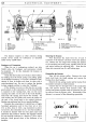
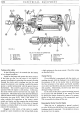
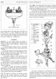
Fig. 20. Distributor
in
exploded form.
I.
Cover.
2.
Carbon brush.
3.
Rotor.
4.
Contact breaker
points.
5.
Contact breaker
plate washer.
6.
Jump ring.
7.
Vacuum control.
8.
Distance collar.
9.
Balance weights.
10.
Cam.
II.
Contact breaker
plate tension
spring,
12.
Capacitor.
MC.
63.
A.
The cable is connected to the distributor by un-
screwing the pointed fixing screws on the inside
of
the
moulding, pushing the cables, which should not be
bared but cut off flush to the required length, well home
into their respective terminals and tightening the pointed
fixing screws.