
Owners Manual


ELECTRICAL
MC. 13. A.
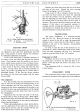
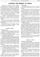
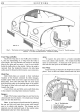
Fig. 21. Fitting a high tension cable terminal.
A.
Cable.
B.
Washer. C.
Cable
strands.
D.
Moulded
terminal.
ELECTRIC
HORN
All horns, before being passed out
of
the works,
are adjusted to give their best performance and will
give a long period
of
service without any attention;
no subsequent adjustment is required.
If
one
of
the horns fails or becomes uncertain in
its action,
it
does
not
follow
that
the horn has broken
down. First ascertain
that
the trouble is
not
due to
some outside source such as a loose or broken
connec-
tion in the wiring
of
the
horn
or a discharged battery;
a short circuit in
the
horn
wiring will cause the fuse
to blow.
If
both horns fail or become uncertain in
action, the trouble is probably due to a blown fuse
or
discharged battery.
If
the fuse has blown, examine
the wiring for the fault
and
replace with the spare
fuse provided.
Horn Adjustment
It
is also possible that the performance
of
a horn
may be upset by the fixing bolt working loose, or by
some component near the horn being loose.
If
after
carrying out the above examination the trouble is not
rectified, the horn may need adjustment, but this should
not be necessary until the horns have been in service
for a long period.
Adjustment does
not
alter the pitch
of
the note,
it
merely takes up wear
of
moving parts. When adjust-
ing the horns, short circuit the fuse, otherwise
it
is liable
to blow. Again,
if
the horns do
not
sound on adjustment,
release the push instantly.
When making adjustments to a horn, always
discon-
nect the supply lead
of
the other horn, taking care to
ensure that
it
does
not
come into contact with any part
of
the chassis and so cause a short circuit.
EQUIPMENT
0/15
Remove the fixing screw from the top
of
the horn
and take off the cover. Detach the cover securing
bracket by springing
it
out
of
its location.
Using a pair
of
4 B.A. spanners, slacken the lock-
nut below the fixed contact
and
rotate the adjusting
nut until the contacts are
just
separated. Then turn
back the adjusting
nut
about
half
a
turn
and measure
the current taken by the
horn
when the horn push is
operated. This current should be between six and seven
amperes.
If
this value is
not
measured, continue to
re-adjust and test, turning the adjusting
nut
in a clock-
wise direction to decrease the current and in
an
anti-
clockwise direction to increase the current.
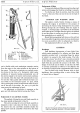
TRAFFICATORS
The Lucas "Trafficator" is a solenoid-operated
unit (see Fig. 23). When the switch on the steering
column is moved to the left or right, the appropriate
indicator arm is raised
and
the bulb, which is incor-
porated in the arm
of
the indicator, automatically
illuminates the arm.
In
order to raise the arm
of
the indicator for re-
placement
of
a bulb or lubricating, switch on the Traffi-
cator and then supporting the arm in a horizontal
position, move the switch
to
the "off" position.
Replacement
of
a Bulb
Withdraw the screw
at
the end
of
the arm and lift
the metal plate; the burnt out bulb may then be
re-
placed. Lower the plate
and
secure
it
by
means
of
its
fixing screw.
The replacement bulb is a Lucas No. 256,
12
volt,
3 watt, festoon.
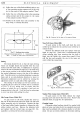
WINDSCREEN WIPER
The windscreen wiper consists
of
an electric motor
and gearbox mounted on the engine side
of
the bulkhead
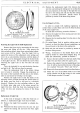
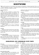
Fig. 22. The electric horn showing adjustment points.
1.
Locknut.
2. Adjusting nut.