
Owners Manual


0/16
ELECTRICAL
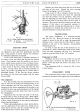
Fig. 23. The Trafficator.
A. Arm catch pin. F. Buffer plate.
B. Arm pivot. G. Bulb contact.
C. Plunger.
H.
Securing tongue.
D. Solenoid.
J. Arm securing screw.
E. Terminal sleeve. K. Arm cover:
and a
:flexible
cable rack mechanism transmits motion
from the motor to the wiper spindles at the bottom
of
the screen. The motor incorporates an overload protec-
tive device in the form
of
a thermostat which under
conditions
of
excessive heating automatically cuts off
the current supply to the motor until normal conditions
are restored, when the wiper will automatically re-start.
To start the wiper, gently pull outwards the wiper con-
trol switch
on
the instrument panel. To park, switch
off by pressing the control switch inwards when the arms
are at the end
of
the stroke.
Do
not try to push the
arms across the windscreen by hand.
No adjustment or lubrication
is
necessary
as
the
gears are fully lubricated before leaving the Works.
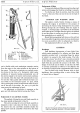
Replacement
of
Arm and Blade Assembly
The method
of
fixing the arm and blade assembly to
the wiper spindle is illustrated in Fig.
24.
The screw securing the arm and blade assembly
is
designed
so
that
it
also takes the form
of
an extractor.
To remove the arm and blade assembly slacken the
fixing screw until the assembly
is
freed from the wiper
spindle.
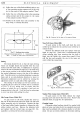
EQUIPMENT
Replacement
of
Blade
To remove the blade, pull the arm away from the wind-
screen and disengage the blade by swivelling
it
upwards.
To clip the new blade in position, insert the curved
"wrist" at the end
of
the arm into the slot
in
the back
of
the blade.
IGNITION AND WARNING LIGHT
The ignition switch, besides forming a means
of
stopping the engine,
is
provided for the purpose
of
preventing the battery being discharged by the current
flowing through the coil windings when the engine
is
stopped. A warning lamp is provided on the instrument
panel which gives a red light when the ignition
is
switched
on and the engine
is
running very slowly or
is
stationary,
thus reminding you to switch
off.
Should the warning lamp bulb burn out, this will not
in any way affect the ignition system, but you should renew
it
as
soon
as
possible in order to safeguard your battery.
The replacement bulb is a Lucas No.
987.
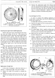
LIGHTING
Headlamps
Each headlamp incorporates a Lucas Light Unit,
which consists essentially
of
a reflector and front glass
assembly provided with a mounting flange by means
of
which
it
is
secured in the body housing. The bulb,
which has a Lucas
"pre-focus" cap,
is
located accurately
in the reflector and is secured by a bayonet-fixed back-
shell which also provides the contact to the bulb. The
design
of
the bulb and its holder is such that the bulb
is
correctly positioned in relation to the reflector and
no focusing
is
required when a replacement bulb
is
fitted.
Cars are fitted with double filament bulbs in both
headlamps, thus providing either a main driving light
or beams that are dipped.
H40. 166. A.
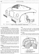
Fig.
24.
Showing the method
of
fixing the windscreen
wiper arm
and
blade assembly to the motor spindle.