
Owners Manual


ELECTRICAL
2
5 MC. 66. A. 4
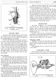
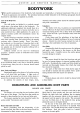
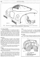
Fig. 25. Headlight glass assembly.
1.
Vertical adjustment screw.
2.
Rubber dust
excluder.
3.
Front
rim.
4.
Rim
securing screw.
5.
Horizontal adjusting screw.
Removing the Light Unit for
Bulb
Replacement
Remove the front rim by unscrewing the rim secur-
ing screw
and
lifting off the rim. Next remove the
dust excluding rubber, when three spring loaded adjust-
ment screws will be visible. Press the Light
Unit in
against the tension
of
the adjustment screw springs and
turn it in an anti-clockwise direction until the heads
of
the screws can be disengaged through the slotted holes
in the Light
Unit
rim.
Do
not
disturb the screws when
removing the Light
Unit as this will alter the lamp
setting.
Twist the backshell
in
an
anti-clockwise direction
and pull
it
off.
The bulb can then be removed.
Place the replacement bulb
in the holder, taking
care to locate
it
correctly. Engage the projections on
the inside
of
the backshell with the slots in the holder,
press on and secure by twisting
it
to the right.
Position the Light
Unit
so
that the heads
of
the
adjusting screws protrude through the slotted holes
in
the flange, press the
Unit
in and turn in a clockwise
direction. Replace the dust excluding rubber so that
its thicker inner edge rests
in the recess around the
Light
Unit
rim. Refit the front rim, locating the top
of
the rim first and securing
by
means
of
the fixing
screw.
Replacement
of
Light Unit
In
the event
of
damage to either the front lens or
reflector, a replacement Light
Unit must be fitted.
(1)
Remove the Light
Unit
assembly
as
already des-
cribed.
(2)
Withdraw the three screws from the unit rim and
remove the seating rim and unit
rim from Light
Unit.
EQUIPMENT
0/17
(3)
Position the replacement Light Unit between the
unit rim and seating rim taking care to see that the
die cast projection
at
the edge
of
the light fits into
the slot in the seating rim and also that the seating
ring is correctly positioned. Finally secure in
position by means
of
the three fixing screws.
Cars for Export to U.S.A.
In
order to comply with Lighting regulations in
certain States a sealed beam unit must be fitted in place
of
the Lucas Light Unit.
To make the conversion, proceed
as
follows:-
(1)
Remove the Light
Unit
from seating and unit rims
as
already described.
(2)
Remove the two packing clips from the slots in the
seating rim.
(3)
Fit
sealed Beam
Unit
in position taking care to
locate
it
so that the three die-cast projections on
the unit locate in the slots
in
the seating rim.
(4)
Refit unit rim and secure in position by means of
the three fixing screws.
(5)
Wiring. Connection
to
the Sealed Beam unit is
made by means
of
a three-point adaptor plug. To
make the connections, proceed
as
follows:-
(i) Remove the three cables from the back shell
of
the
Light
Unit and bare cables for approx. l-in.
(ii) Remove the adaptor from the Sealed Beam Unit.
Note.
It
will be observed that the rear
of
the adap-
tor is marked
"Ground",
"Pass" and "Drive".
(iii) Remove the three spring contacts from the adaptor.
(iv) Solder the core
of
the Black cable to one
of
the
spring contacts and fit the contact in the recess
of
the adaptor marked
"Ground".
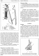
Fig. 26. Headlight unit.
A. Light
Unit:
B.
Backshell: C. Vertical adjustment:
D.
Horizontal
adjustment: E. Bulb holder: F.
Dust
excluder.