
Owners Manual


0/18
ELECTRICAL
(v)
Solder the core
of
the Red and Black cable to one
of
the remaining spring contacts and fit the con-
tact in the recess
of
the adaptor marked "Pass".
(vi) Solder the core
of
the Blue cable to the remaining
spring contact and fit the contact in the recess
of
the adaptor marked "Drive".
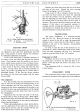
(vii) Finaily fit the sealed beam unit assembly to the
lamp body,
as
already described.
2
3
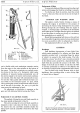
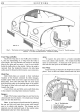
MC. 64. A.
Fig. 27. Headlamp beam setting.
I.
Distance between lamp centres.
2.
Concentrated area
of
light.
3.
Height
of
lamp centres from ground.
Setting
The lamps should be set so that the main driving
beams are straight ahead
and
parallel with the road
surface
and
with each other.
If
adjustment is required,
remove the rim
as
described in page 0/17. Set each lamp
to the correct position in the vertical plane by means
of
the vertical adjustment screw
at
the top
of
the reflector
unit. Turn the screw in a clockwise direction to raise the
beam and
in
an anti-clockwise direction to lower it.
Horizontal adjustment can be altered by turning the
adjustment screws on each side
of
the Light Unit.
The setting
of
the lamps can be best carried out
by
placing the car in front
of
a blank wall
at
a distance
of
25-ft. (7.
62
m.), taking care,
of
course, that the
surface on which the car is standing is level and
not
sloping relative to the wall.
It
will be found an advantage
to
cover one lamp while setting the other.
Side Lamps (Lucas Model 516)
To gain access to the bulb, slacken the screw
at
the rear
of
the lamp body when the front rim and bulb
holder assembly may be withdrawn. Squeeze the legs
of
the lamp holder bracket together
to
release the rim,
rubber washer, and lens. Remove the defective bulb
and replace with the correct type, see page
0/1.
Re-
assembly is a reversal
of
the above instructions.
EQUIPMENT
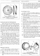
Fig. 28. Removal
of
the glass
of
the stop-tail lamp.
Stop-Tail (Lucas Model 488)
To gain access to the bulb, pull back the outer
rubber lip to release the rim and the inner rubber lip to
release the lens.
Remove the defective bulb and replace with type
listed on page
0/1.
(This bulb is manufactured with
off-set securing pins, thus ensuring that the bulb is
fitted into the holder the correct
way
round.) First,
refit the lens and secondly, the rim to the inner and
outer rubber lips respectively.
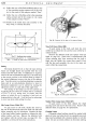
Fig. 29.
Number
plate illumination.
Number Plate Lamp (Lucas Model 467)
To gain access to the bulb, slacken the single
securing screw and remove the front cover. Remove the
defective bulb, see page
0/1
for replacement.
Cleaning Lamps
Chromium plated surfaces should be washed with
plenty
of
water, and when the dirt is completely removed,
they must be polished with a chamois leather or soft dry
cloth.
Do
not
use metal polishes on chromium plating.