
Owners Manual


BODYWORK
P/7
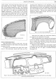
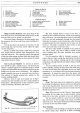
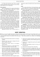
Caption for Fig. 10.
1.
Door
shell.
6.
Window
front
channel. 11.
Door
closing handle.
2.
Window glass.
7.
Upper
hinge. 12.
Door
opening handle.
3.
Window
rear
channel.
8.
Lower hinge.
13.
Window
winding mechanism.
4.
Window
moulding.
9.
Door
lock exploded. 14.
Door
inner casing.
5.
Louvre assembly.
10.
Window winding handle.
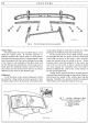
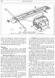
Caption for Fig.
11.
1.
Door
lock mechanism.
6.
Arm
rest (door closing handle).
11.
Window front channel.
2.
Window
winding handle. 7.
Window moulding. 12.
Window
glass.
3.
Door
opening handle. 8.
Louvre assembly.
13.
Upper
hinge.
4.
Window
winding mechanism.
9.
Door
shell.
14.
Lower hinge.
5.
Door
inner casing.
10.
Window
rear channel.
Hinges and Door Removal: The upper hinge
of
the
front door has four recessed-headed screws to
fix
it
to the
door and four more to secure
it
to the pillar.
The lower hinge is fastened in the same manner with
the exception that
it
has only three screws holding
it
to
the door.
For
the rear doors the position
is
reversed,
it
is
the
lower hinge that has the four screws whilst the upper
one has only three.
There
is
a check strap fitted to each door, front and
rear, which must be released when dismantling a door
from the bodywork. This operation entails the removal
of
the door inner casing, an item which has already been
described, and extracting the pin that retains the check
strap within the door frame.
Door Locks and Handles: To remove an interior
door handle
is
quite a simple process. The chrome cup
washer
is
pushed against the concealed spring
in
which
position
it
is held whilst the peg which passes through the
handle and the lock stem is withdrawn. The complete
handle assembly can now be removed from the door.
This method
of
handle securing also applies to the
window winding handle.
Before a lock or outer door handle can be depo-
sitioned, the inner handles and door casing should be
dismantled, a full description
of
this operation
is
given
under the heading "Windows and Doors".
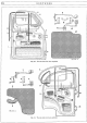
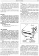
Fig,
12.
A
door
handle
and
its two securing screws.
The lock, whether fitted to front or rear door,
is
secured by four round head screws, visible on the opening
edge
of
the door.
By
extracting these screws
it
is possible
to lift out the lock mechanism through the door panel.
Similarly, the remote control mechanism, after the long
connecting link has been released, can be taken out
of
the door. The latter
is
secured by three screws in the
front door and three in the rear door.
The door outer handle is attached to the panel by
two 2 B.A. screws only, one
of
which is visible on the
door's opening edge, the other accessible from within
the door panel.
On
the occasions when
it
becomes necessary to
remove the door inner casing, the opportunity should be
taken to oil the window winding and the door locking
mechanisms, through the holes provided in the door shell,
see
Fig.
10.
An extra locking device is fitted to the rear door
interior handles, locking the doors from the inside only.
To lock the left-hand and right-hand doors, turn their
escutcheons in a clockwise and anti-clockwise direction
respectively.
It
should be noted that this device will
not function
if
the door handle is already in the locked
position.
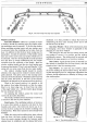
Seating
Front: The front seats can
be
adjusted for position
by pressing the adjustment lever inwards and sliding the
seat to the required place. Each seat runner is fixed to
the body floor by four setpins and can be easily removed
should the necessity arise.
Rear: The rear seat
is
of
the "drop-in" type, located
in position by two pegs, one at each foremost corner
which
fit
in the holes provided in the seat platform.
The rear squab is held by a screw into each wheel-
arch
and
by two at the top edge
of
the squab, accessible
within the boot. The squab should then be lifted straight
up to free the two top metal tongues.
Waist Moulding
The chrome waist mouldings are clipped to the body
by special spring clips. Removal
of
these mouldings