
Owners Manual


P/8
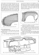
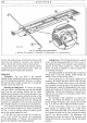
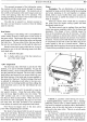
BODYWORK
H40, 173.
A.
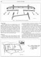
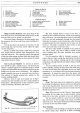
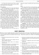
Fig. 13. The sliding roof locking mechanism.
A.
Slide bar.
B.
Locking bar. C. Keep-plate.
D.
Adjusting screw. E. Cranked lifting rod.
involves the simple process
of
levering the chrome strip
away from the bodywork. However, care should be
taken to ensure that no
harm
comes to the paintwork.
All chrome strip is secured in this manner with the
exception
of
the rear wing protection plates. These are
secured through the wing by three setscrews.
Sliding Roof
Description: The
roof
fitted is the patented
Pytchely design which should require
very
little attention
from the mechanical standpoint. However,
it
is impor-
tant that the water troughs are kept free
of
obstruction
and the runners free from rust.
Removing the Sliding Roof: To remove the sliding
roof, first unlock
it
and
then take away the side draught
strips from the
roof
opening. Release the two screws
holding the two brackets
at
the forward side edges
of
the
panel and push these brackets outward and clear
of
the
edges. This sliding portion
of
the roof may now be lifted
at
its front end and pulled clear
of
the car. During this
operation
it
is advisable
to
cover the front canopy with
felt, or similar material,
as
a protection for the paintwork.
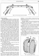
Two operators should be employed when replacing
the roof; the person inside the car guides the slide bar
(A) Fig.
13,
into its housing within the channel as the
one on the outside replaces the roof.
If
the slide bar does
not
enter the housing cor-
rectly
it
will override the channel and consequently
tear the fabric lining, or
"ruck-up" the protective felt
glued to the underside
of
the locking channel.
Locking Device: The locking mechanism is encased
with a channel running centrally from front to rear
of
the sliding
roof
panel. This channel is spot-welded into
position
and
the whole enclosed by a fabric covered
board. The latter is clinched to a frame mounted with-
in the sliding
roof
panel.
The locking handle is secured through its head by a
female screw to the lock spindle, whilst beneath the
handle
is
fitted a double spring washer.
Should adjustment to the locking mechanism be
necessary, first release the fabric board
at
the rear edge
of
the sliding roof, which will give access to the adjusting
screw situated towards the rear
of
the locking channel.
The adjustment is made
by
slackening this screw, push-
ing the screw head as far forward
as
possible and then
retightening. Test the
roof
mechanism to ensure
that
it
will lock the
roof
panel in any desired position before
replacing the lining.
The workings
of
the mechanism are simple but
effective.
By
turning the handle, an eccentric peg is
moved through
90
degrees, thus pushing the bar
(B)
Fig.
13,
to the rear with a slight movement
to
the left.
This bar incorporates a taper
at
its rear end which
slides against an opposing taper
of
a small keep-
plate
(C) and forces the latter over to the left to butt-up
hard against the slide bar (A) thus securing the sliding
panel in any desired position.
On adjustment, the
adjusting screw keeps the tapers
of
the keep-plate and
locking bar hard up to one another when in the locked
position.