
Owners Manual
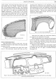


BODYWORK
P/11
(c)
If
the correct operation in (a) or (b) is
not
being
obtained, adjustments must be made
as
for
(c)
in "Heat-
ing/Ventilating Control Adjustment".
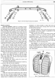
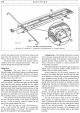
Heater Removal
Before withdrawing the four setpins which hold the
heater to the scuttle, there are other items
of
heater
equipment that have to be disconnected.
The Bowden cables operating the air valve and de-
mister valves should be disconnected
at
the heater unit.
Then the demister pipes should be disconnected from
the unit by releasing their clips
at
the heater end. Here
a little difficulty may be experienced due to the fact that
to gain access to these clips the valances beneath the
fascia must be removed. The two
hot
water pipes are
each secured to the heater connections by clips. These
must be released and in the same manner the main air
pipe must be dismantled from the heater box.
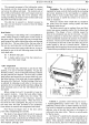
The fan motor does
not
normally require servicing
as
the bearings are packed with lubricant on assembly.
To remove the fan from its mounting, however, merely
entails first releasing the hose clips and pulling the hose
free
of
the fan outlet. Then disconnect the single elec-
trical lead
at
its local snap joint connection and finally
remove the three nuts and washers from the fan body
securing studs. The motor and fan
as
a combined unit
can now be removed from its mounting.
Replacing the heater unit, or fan and motor, is
achieved
by
simply reversing the given removal instruc-
tions.
Radio
For
tuning and setting up
of
the push buttons, the
operator should refer to the small booklet issued with
each radio set when supplied
by
the manufacturers.
Removing the Radio: Should
it
become necessary to
remove the radio set for any reason, the four bolts
securing the carrier bracket to the scuttle bulkhead must
be withdrawn. The set complete with bracket can then
be retrieved from beneath the dash panel inside the car.
When releasing the cables from the set be sure to identify
them with their relative sockets for ease
of
replacement.
Removing the Control Head: The control head is
situated in the glove box compartment on the driver's
side. To remove the control head the compartment lid
must be opened and the flexible control wires and cables
disconnected. By removing the four retaining screws,
two each side, the face plate complete with control head
and
"U"
bracket may be lifted out
of
the compartment.
Loudspeaker: The speaker is hidden from view
behind the fabric lining
of
the canopy immediately above
the windscreen. With the lining released and peeled
back
it
becomes possible to extract the screws that retain
the speaker in place, when the cables should be dis-
connected
at
its rear.
BODY REMOVAL
JN
the rare event
of
complete body removal being necessary, the operator should read the preceding itemised part
removals
as
there are fifteen preliminary operations to be effected before
it
is possible to release the body securing
bolts and thereby separate the coachwork from the chassis. These fifteen operations are outlined in the following
paragraphs:-
1.
Disconnect the battery leads and remove the battery
complete.
2.
Dismantle both front and rear bumpers from the
chassis complete with arms.
3.
Disconnect the electric cables
at
the dynamo,
starter and coil.
4.
Break the snap connections, near the radiator frame,
of
the direction indicators and horn cables.
5.
Drain the cooling system, extract the thermometer
bulb from its tank position, then release the radiator
from its mounting, after releasing the brake supply
tank, and
if
it
cannot be adequately supported
release the hoses and remove the radiator complete.
6.
Remove the set bolts that secure the radiator frame
to the chassis front cross member.
7.
Release the speedometer cable
at
its gearbox union.
8.
Disconnect the throttle and choke controls
at
their
carburetter connections, also the heater pipes from
the heater box.
9.
Separate the oil gauge
flex
pipe from the scuttle
copper pipe.
10.
Disconnect the hand brake control
at
the base
of
the control rod.
11.
Disconnect the steering box from the chassis.
12.
Remove the gear lever operating arm, free the
change control rod from the chassis, also disconnect
it
at
the mechanism and then extract the rod from
the bodywork.
13, Remove the pads from the brake and clutch opera-
tion pedals and then remove their floor board pads.
14.
Release the fuel delivery pipe from its tank union
having first drained the tank.