
Owners Manual

BODYWORK
P/13
15.
Under the floor carpet
at
each side
of
the body are
three small panels and one each side
of
the gearbox
cover. With these panels removed, access is gained
to the heads
of
the body holding down bolts.
At each side
of
the body there are
five
sets
of
nuts,
bolts and washers and rubber pads for securing the body,
through brackets, to the chassis. Further, through the
chassis cross bracing members each side
of
the gearbox
there is one more nut, bolt, washer and rubber pad.
The body may now be removed from the chassis
as
one complete unit, using a suitable sling which should
lift the rear
of
the body first. Lifting operations should
be slow and the body carefully pulled rearwards to clear
the remaining controls.
Replacing the body is an exact reversal
of
the
removal instructions.
DISMANTLING AND ASSEMBLING BODY PARTS
COMMERCIALS
In
most instances the body parts
of
the Van,
Countryman and
Pick-Up are identical and only where
differences occur will they be mentioned individually.
Bonnet Top
Described in Section D, page
18.
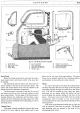
Front Wing Assembly Complete
The front wing assembly compnsmg both front
wings, flitch plates, head and side lamps, radiator grille
and front apron can be removed
as
a complete unit.
First remove the two baffle plates located under each
front wing
at
the rear. These plates are secured by four
setpins to the scuttle and by two setpins to the wing.
On each side, remove the two setpins which hold the
rear
of
the outer wing half
to
the scuttle. Then remove
the one bolt on each side
of
the car which holds the rear
of
the engine flitch plate to the scuttle. These bolts are
fitted with plain and spring washers.
Disconnect the headlamp cables
at
their nearest
convenient snap-on connectors and then remove the
four bolts securing the flitch plates on each side
of
the
radiator stay bar. The three lower bolts are inserted
from inside the wing and its front support bracket. They
have a large plain washer under the bolt head with a
plain and spring washer under the nut. The top securing
bolt, inserted from the radiator stay
bar
bracket through
the flitch plate, has a plain and spring washer under the
nut.
The complete assembly can now be lifted clear.
Replacement is an exact reversal
of
the removal instruc-
tions.
Front Wings and Flitch Plate
The two halves
of
a front wing can either
be
removed
as
one unit or
if
required the outer half only need be
removed.
To remove the outer half, first take off the lamp
front cover and unscrew the two outer securing pins
which hold the lamp body
to
the wing. These securing
pins are held by brass nuts under the wing and the nuts
have solid rear faces to prevent corrosion
of
the securing
pins. Remove side lamp which
is
held
by
three brass nuts.
Then release the two bolts holding the outer half
of
the front wing
to
the baffle plate
at
the rear underside
of the wing and release the two bolts which hold the rear
upper flange
of
the outside wing to the scuttle.
The outer
half
of
the wing can now be removed when
the twelve bolts, which
hold
the wing to the front apron
and inner wing, have each been removed.
Replacement is a reversal
of
the above, but make
sure that the beading is properly fitted between the wing
halves and that each
of
the securing bolts are fitted with
plain and spring washers.
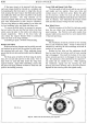
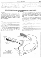
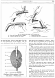
B
Fig. 17. Front
wing
and flitch plate.
A.
Outer wing.
B.
Beading. C. Inner
to
outer wing
bolt hole. D. Headlamp securing point. E. Inner
wing.
F.
Inner wing
to
flitch plate bolt hole. G.
Flitch plate.