
Owners Manual

P/14
BODYWORK
If
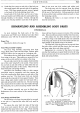
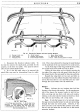
the inner wing is to be removed, both the inner
and outer wings should be removed
as
a complete unit
by
detaching the
five
front apron to wing bolts, the six
bolts securing the inner wing to the flitch plate and the
rear
baffle plate bolts and outer wing bolts to the scuttle
mentioned previously. The
wing
assembly can be
removed complete when the head and side lamp cables
have been disconnected at their snap-on connectors.
The two wing halves are held together
by
ten bolts and
by four headlamp bolts, and three side lamp nuts.
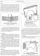
To remove the flitch plate it
is
necessary to unscrew
the two bolts at the rear and the four bolts at the front
which secure the plate to the scuttle and radiator stay
bracket respectively. Three of the front bolts
will
also release the support bracket which
is
positioned
under the front of the wing assembly.
Assembling
is
again a reversal of dismantling.
Bumpers
and
Apron
Both front and rear bumpers can be quickly removed
and replaced
as
each is held in position by easily access-
ible securing bolts and nuts. When replacing always
ensure that the nuts have spring washers and are tightened
firmly.
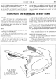
The front apron
is
held
to
the front wings
by
twelve
bolts,
five
on each side and two in the centre. Two
of
these bolts on each side help secure the wing front
support brackets. Again when assembling, ensure that
the plain and spring washers are fitted to each bolt and
position the beading correctly.
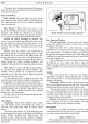
H40. 303,
A.
Lower
Grille
and
Bonnet
Catch
Plate
The lower grille
is
held at each side
by
one nut, bolt
and washer and two setpins; three nuts,
bolts and
washers secure
it
to the front apron. Before the grille
can be removed a further two nuts and bolts, situated
behind the grille, holding the catch plate stay to the apron
must be released. Also disconnect the bonnet control
cable and the electrical wiring from the catch plate.
Rear
Wheel
Covers
With the exception
of
the Pick-Up, the latest models
have the rear wheel cover incorporated
in
body side
panel pressing. The Pick-Up and early models have
separate wheel covers secured by four screw headed bolts
of bayonet type fixing.
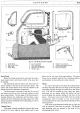
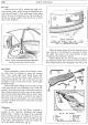
Windscreen
The windscreen is held in position
by
two securing
bolts in each windscreen pillar. Access to these bolts
is
obtained by removing the side mouldings each held in
position by two screws.
Release the four bolts and the windscreen should
then be raised from the bottom until its lower securing
lug
is
disengaged. Then pull the bottom
of
the wind-
screen outwards and down to disengage the top securing
lug. This operation
is
best achieved by two
operators-
one inside and one outside the car. When replacing
the windscreen engage the top securing lug first,
allowing the bottom securing lug to drop into position.
Replace the four securing bolts and tighten evenly.
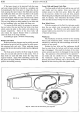
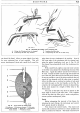
Fig·.
18. Fascia with the instrument panel exploded.