
Owners Manual

P/20
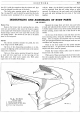
BODYWORK
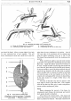
Boot Lid
Remove the
boot
lid
by
undoing the single bolt,
with nut
and
washer, which secures the supporting stay
to
the
boot
lid
bracket.
From
each hinge, on
the
under
side
of
the
boot
lid, unfasten the two nuts
and
take off
the
flat
and
spring washers when the
lid
can
be lifted
clear
of
the bodywork. ·
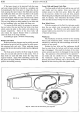
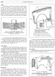
Fig. 27. Interior of the Boot showing the Hinge Nuts.
Inset shows stay fixing to boot lid bracket.
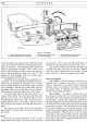
Rear Panel
Before attempting to detach the rear panel, remove
the spare wheel
by
releasing its setpin
and
securing
plate. Then extract eight metal thread screws, with
cup washers, from the panel inner casing. Remove the
casing
and
disconnect the wires
to
the twin stop
and
taillights
as well as those from the rear number plate
illumination light.
Remove the rubber sealing strip from the
top
edge
of
the panel
and
drill
out
the
thirteen
"pop"
rivets now
exposed.
From
the
bottom
edge
of
the panel extract the
three visible countersunk screws, with nuts and washers.
Also from the
bottom
edge, drill
out
the ten
"pop"
rivets.
Each side
of
the rear panel is secured to the body by
three bolts, with nuts
and
washers.
It
is only necessary
to slacken off these three bolts
to
release the rear panel
from the body.
Windscreen
The windscreen
of
the A40 Sports
is
secured in
position by the Clatonrite (Patented) Self Sealing
Weather Strip.
Owing
to
the
shape
of
the windscreen
frame the rubber seal has
to
be fitted in two parts, one
piece for the
bottom
and the other for the sides
and
top
of
the frame.
The
installation
of
this seal requires the
use
of
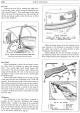
the makers' special tool, Fig.
29.
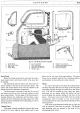
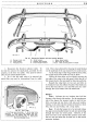
Fig. 28. Rear Panel.
1.
Holes
in
top flange for
"pop"
rivets.
2.
Side
securing points.
3.
Bottom
flange holes for
"pop"
rivets.
4.
Countersunk screw holes.
When the broken pieces
of
the old windscreen have
been removed,
it
will probably be necessary
to
remove
the rubber seal owing
to
the small particles
of
glass
remaining in the windscreen channel.
Before refitting the seal, first lubricate the edge
of
the windscreen frame with a solution
of
soap
and
water.
If
the original seal has been damaged in any way, a new
H40. 224. A.
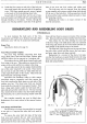
Fig. 29. Tool Assembly.
I.
Key
5.
Hook
(small).
2.
Handle.
6.
Eye (large).
3.
Post.
7.
Eye (small).
4.
Hook
(large).
8.
Spur.
9.
Inset showing threading
of
filler strip.