
Owners Manual

BODYWORK
P/21
H40. 222.
A.
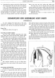
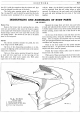
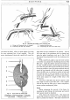
Fig. 30. Illustrating the Fitting of the Clatonrite Seal.
A. Fitting the Windscreen into its channel. C. Inserting the filler strip.
B. Lubricating the filler strip channel.
D.
Compressing the ends
of
the filler strip.
one should be fitted. Allow an extra eighth
of
an inch
for every estimated foot
of
seal required. This will
ensure weatherproof joints and a good
fit
all round the
2
3
4
5
6
7
H40. 223.
B.
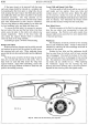
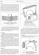
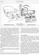
Fig. 31. Cross Section of Sealing Strip.
1.
Windscreen.
2.
Windscreen channel.
3.
Filler strip.
4.
Filler strip channel.
5.
Main seal.
6.
Windscreen
frame channel.
7.
Windscreen frame.
edge when the new windscreen is in position. Now
fit
the lower edge
of
the windscreen into its channel and,
using the special installation tool, see A, Fig.
30,
lift
the ehannellip and gradually work the windscreen into
position.
With a small brush, apply a soap and water solution
to the filler strip channel thus facilitating the entry
ofthe
filler strip. Again the makers' special tool will have to
be used. Thread the filler strip through the handle
and
eye
of
the tool, insert the tool into the filler strip channel,
as
near
as
possible
to
one
of
the joints, and draw the tool
round the top channel until the other joint is reached.
Allow the filler strip to overlap two inches
at
both ends
and with the spur on the tool handle, see D, Fig.
30,
compress the overlapping filler strip into its channelling.
In
the same manner fit a length
of
filler strip to the
bottom seal.
The ends
of
the filler strip must be mitred to the
same angle
as
those
of
the main seal. This, together
with the fact that the filler strip is under compression,
ensures perfect weatherproof joints.
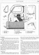
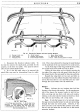
Fascia
Before attempting the removal
of
the fascia, by
releasing the main fixings, the instrument and control
knob panels should be detached.
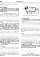
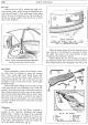
First remove the control knobs. The choke and
starter pull controls are screwed on to their spindles and
held in position by locknuts. The heater control knob