
Owners Manual


BODYWORK
P/25
seat cushion
and
then tip forward the backrest, release
the locking handle and slide the seat rearward out
of
its runners. Each seat runner
is
secured to the floor by
four setpins.
The rear seat
is
of
the "drop-
in"
type
and
is easily
removed. To take out the rear seat squab, first release
the press stud fastening midway
on
the hood lip. Tip
the squab forward and withdraw two screws from each
hinge at the base
of
the squab.
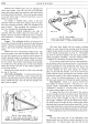
Heater
Before removing the heater, first drain the cooling
system and then slacken off the two clips that secure
the flexible hose to the two pipes protruding forward
through the scuttle from the heater unit. Pull off the
flexible hoses from these two pipes, disconnect the two
electrical cables to the heater and release the two screws
holding the de-mister piping to the rear
of
the heater.
Before the unit can be lifted from its compartment, the
plate immediately on top
of
it
must be removed by un-
doing three bolts, with nuts and washers,
and
six set-
screws. The heater is held
in
position by felt pads
at
top and bottom.
Full access to the de-mister pipes can only
be
obtained
if
the fascia
is
removed. The discharge vents,
at
the end
of
the de-mister pipes, are secured to the
body by two self-tapping metal screws.
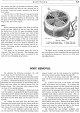
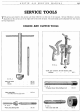
Fig. 36. Heater.
1.
Outlet to de-mister pipes.
4.
Water inlet pipe.
2 and
3.
Heater motor cables.
5.
Water outlet pipe.
The heater
motor
bearings are packed with lubri-
cant when the unit is first assembled and servicing should
not
normally be necessary as there are no other parts
requiring attention.
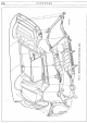
BODY REMOVAL
By
adopting the following procedure, the A40
Sports body may be removed from its chassis.
(a) Remove the bonnet top and release the control
cable
at
the catch. Release the battery terminals
and
lift
out
battery. Dismantle the harness for ease
of
working.
Disconnect the snap connectors
at
the left-hand side
of
flitch plate
and
release the lighting harness from the
radiator frame. Also release the snap connectors from
the base
of
the steering column.
(b) Disconnect the following : thermometer bulb
from the radiator, oil gauge flexible pipe from the engine
block, high
and
low tension wires from the coil, throttle
ann
and
choke cable from the carburetter linkage, brake
:fluid
tank from the flitch plate and the leads from the
dynamo.
(c)
Detach the earth cable from the flitch plate.
Disconnect the bottom cable from the starter switch and
from its clip
on
the scuttle. Drain the cooling system
then release the two water pipes
at
their heater unions.
(d) Pull out the trafficator control and take off
the steering wheel. Having released the steering column
support bracket and the clip securing the handbrake
remove the column and gear change (see page I/5).
(e)
Remove the seats, carpet
and
felt underlay.
Strip off the sound insulating material glued to the
floor.
(f) Unscrew the heads
of
the brake and clutch
pedals and remove the toe boards. Five setpins and
two metal thread screws hold the driving side toe board
in position while
five
setpins and three metal thread
screws secure the passenger side toe board. Release the
short tunnel, covering the front universal joint
of
the
propeller shaft, which is held by four screws. Also re-
move the gearbox rubber cover secured by twelve screws.
(g) Detach the floor plate on the driving side, held
by four metal thread screws, the one
on
the passenger
side is held by three screws. Remove all the metal thread
screws
that
secure the body, the body side floors to the
chassis and those that secure the body to the chassis
along the front edge
of
the rear seat platform.
(h) Remove the rear bumper, complete with
brackets. The front bumper need not be released. Drain