
Owners Manual


COOLING
SYSTEM
B/3
5.
If
for any reason the mixture is lost and the system
is
filled with water only, remove the painted disc
on
the
header tank.
Protection
by
Draining
On vehicles where anti-freeze is not used the follow-
ing precautions must be taken during frosty weather to
obviate any damage due
to
freezing
of
the cooling
system.
When heavy frost is imminent, the cooling system
must be completely drained.
It
is not sufficient merely
to cover the radiator and engine with rugs or muffs.
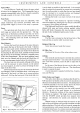
There are
two
drain taps,
one
of them
on
the offside of the
cylinder block, and the other
at
the base of the radiator
block. Both taps must be opened
to
drain the system and
vehicle must
be
on
level ground
while
draining. The drain
taps should be tested
at
frequent intervals by inserting
a piece
of
wire to ensure that they are clear. This should
be done immediately the taps are opened, so that any
obstruction freed by the wire may be flushed out by the
water. The draining should be carried
OJ.It
when the
engine is hot.
When completely drained the engine should be
run for a timed minute to ensure that all water has been
cleared from the system. A suitable notice should then
be affixed to the radiator, indicating
that
the water has
been drained.
As
an alternative, place the radiator
filler cap on the driver's seat or leave the bonnet un-
locked
as
a reminder to fill the cooling system before
using the car again.
N.B.-
If
a heater is fitted, under no circumstances
should draining
of
the cooling system be resorted to
as
an alternative to the use
of
anti-freeze, due to the fact
that complete draining
of
the heater unit, by means
of
the cylinder block and radiator drain taps, is
not
possible.
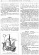
Flushing the Radiator
If
there is anti-freeze in the cooling system, obtain
a receptacle large enough to hold the contents
of
the
radiator and the engine, placing this under the drain tap.
Remove the radiator filler cap and open the drain
tap. (Turn the tap lever
UP
to open
and
DOWN
to
close.)
On completion
of
the draining remove the recep-
tacle and then proceed to flush the radiator from a hose
or other supply
of
clean water.
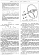
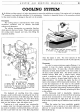
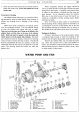
WATER
PUMP AND FAN
H40.
148. C.
Fig. 5. Water pump assembly.
1.
Oil plug and washer.
2.
By-pass pipe.
3.
Woodruff key.
8.
Carbon
sealing ring.
9. Distance piece.
10.
Felt retainer, outer.
15.
Grease retainer.
16.
Spring ring.
17.
Fan
blade.
4.
Nut
for
spindle.
5.
Gland
spring.
6.
Locating cup.
7.
Rubber
seal.
11.
Felt ring.
12.
Felt retainer, inner.
13.
Bearings.
14.
Bearing distance piece.
18.
Fan
and
pump
pulleys.
19.
Pump body.
20.
Pump spindle.
21.
Water impeller.