
Owners Manual


FUEL
SYSTEM
C/3
H40. 265.
J\,
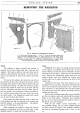
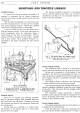
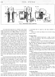
Fig. 4. The Sports throttle
Jinlmge
and jet levers.
1.
Throttle adjuster. 4. Choke cable securing
2.
Fuel feed connection. point.
3.
Main
jet
adjusting nut.
5.
Jet lever connecting rod.
6.
Throttle connecting arm.
The
movement is continued through a bell
crank
lever
which, in turn,
is
fixed to
the
common main throttle
rod
by a further ball
joint
connector.
In
Fig.
4,
it can be clearly seen
that
the
two S.U.
carburetters have
their
jet
levers synchronised by a short
cranked rod.
At
the rear carburetter this rod is linked
to
the
jet
lever
by
a split pin, whilst
at
the
foremost
carburetter the rod
is
secured to the
jet
lever by two nuts.
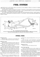
Exhaust
Pipe (Saloon)
Fitted
in three separate parts, the exhaust pipe
assembly is held in position by two brackets to the chassis
frame and by the manifold studs.
To
remove the exhaust pipe from the chassis
proceed as
follows:-
Disconnect the bracket from the underside
of
the
rear cross member
of
the chassis by releasing the single
self-locking nut from lts stud.
Do
not
lose the rubber
mounting bush.
Next slacken the two nuts and bolts
of
the pipe clip
immediately before the silencer.
Pull the tail pipe and
silencer to the rear
in
order to clear the down pipe.
Lower the silencer end
of
the tail pipe
and
extract it
from the chassis frame by taking it forward.
Finally the down pipe. Disconnect the pipe from
the three manifold studs,
then
lower the pipe
and
take it
forward from the chassis.
Note: The exhaust pipe on the commercials
is
removed in the same
manner
as for the saloon with the
exception
that
the tail pipe is fastened
to
the right-hand
side
of
the chassis rear cross member.
Exhaust
Pipe (Sports)
Fitted
in
two parts,
the
exhaust pipe assembly
is
held
in
position
by
two brackets to the chassis frame
and
by the manifold studs.
To remove the exhaust pipe from the chassis
proceed as
follows:-
Disconnect the bracket from the underside
of
the
rear cross member
of
the chassis by releasing the setpin
and
self locking nut.
Do
not
lose
the
two rubber
mounting pads.
Next slacken the
nut
and
bolt
of
the pipe clip
immediately before the silencer.
The
silencer can now
be removed by pulling rearwards.
Undo
the
two setpins
from
the
bracket, situated
at
the
rear
of
the
boxed
part
of
the chassis, which holds the rear portion
of
the down
pipe in position. Remove
the
three nuts
and
flat washers
which
hold
the down pipe
to
the manifold. Lower the
pipe
and
remove from beneath
the
car.
Note.-Down
pipe
and
silencer can be removed as
one
if
so desired.
G.S.4.
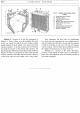
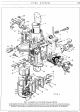
CARBURETTER
GENERAL
DATA
Make
Type
Choke tube
Main
jet
...
Zenith
30
VIG-8
25
90
The
carburetter is
of
the
Zenith downdraught type
which embodies
an
accelerating
pump
and
economy
device. A fully automatic strangler flap interconnected
with
the
throttle is also incorporated for starting
purposes.
The
strangler promotes
rapid
warming
up
after
the initial engine firing has been obtained.
Compensating
jet
Slow running
jet
...
Needle
and
Seating
Pump
Jet
...
Working Description
65
50
1.5
50
Petrol enters
the
carburetter
at
the
union and
passes on to reach
the
needle seating. Unless the float
is already lifted against the needle by
petrol
in
the float
chamber the petrol will continue its course past the
needle into the float chamber.
It
continues
to
flow