
Owners Manual
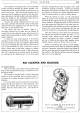

FUEL
at
normal
driving speeds.
In
order
to obtain economical
running
at
such speeds
and
yet ensure faultless accelera-
tion, a controlled
and
measured supply
of
mixture is
necessary when the
throttle
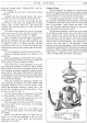
is opened suddenly. This
is
provided
by
the
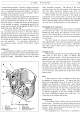
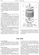
accelerator pump.
Operation
of
the
pump
coincides with the depression
of
the accelerator pedal.
By
means
of
an
interconnection
with the throttle lever the
pump
rod
8 (Fig.
6)
forces
down
the
piston
15
against
the
action
of
the
spring
16
as the
throttle
is opened. Consequently
petrol
in
the
pump
well14
is forced
out
through
the
drilling
12
in
the
base
of
the
well. See also Fig.
7.
Fuel
cannot
return
to
the
float
chamber
because
of
the
non-return
type inlet valve
13.
The
only
outlet
is
through
the
ball
valve
11
to
the
pump
jet
9
and
is then
ejected from
the
emulsion block beak,
in
the
form
of
a
fine spray,
into
the
barrel
of
the
carburetter.
From
here
it
is
carried
by
the inrushing air stream past the throttle
into
the
manifold.
In
consequence depression
of
the accelerator pedal produces instantaneous engine
response.
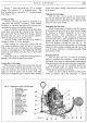
Adjustment
The
carburetter
settings have been selected as most
suitable for
the
engine after extensive experimental work.
Consequently very little
adjustment
to
the
carburetter
should be needed. Adjustments should only be
made
2 1
3
4
6
7 8
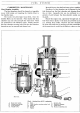
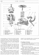
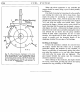
Fig.
7.
The accelerating pump.
1.
Ball valve.
5.
Pump well.
6.
Pump spring.
7.
Drilling to
pump
well.
2.
Pump
jet.
3.
Emulsion block beak.
4.
Pump piston.
8. Non-return valve.
SYSTEM
C/7
when absolutely necessary.
The
setting
of
the slow
running mixture
and
the idling speed
of
the engine are
the only likely alterations needed,
apart
from an
occasional cleaning
of
its
jets
and
float
chamber
bowl.
When trouble
with
the
running
of
the engine is
experienced do
not
assume
that
it is always due
to
the
carburetter. Check all
other
possible causes
of
trouble
such as sparking plugs, timing
of
ignition
and
condition
of
valves, before making alteration to the carburetter.
Dismantling of the Carburetter
Before dismantling, ensure
that
all parts, the hands
and the bench are clean.
The
hand
should be placed
beneath the bowl during this operation so
that
on re-
moval
of
the retaining bolts
it
will
drop
into the hand.
(Economy note:
petrol
in
the
bowl
can
be emptied back
into the tank.)
The jets should be removed occasionally and
thoroughly cleaned.
One
of
the retaining bolts
is
squared
at
the
end
to fit into
the
jet
covers and jets. This facili-
tates their removal when used
in
conjunction with a
suitable spanner.
Cleaning the
Jets
When
cleaning the jets
do
not
pass anything through
them-such
as
wire-that
is
likely
to
damage the
carefully calibrated orifices.
The
most
satisfactory
and
efficient
method
is
to
blow
through
them with air, free
from moisture,
and
wash with clean petrol. This should
remove any obstruction
and
will leave the jets un-
damaged. The sizes
of
all jets are clearly
numbered-
the
larger
the
jet
the greater the number.
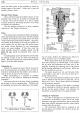
The
slow
running
jet
is
provided with a screw-driver slot
to
enable
it
to
be removed. This applies also
to
the
screw
in
the
capacity tube.
Float
If
there have been signs
of
flooding the float may
be suspected
of
being punctured.
To
remove the float
release the large-headed screw
at
the side
of
the
float
chamber
and
immerse in boiling water, when rising
bubbles will indicate the exact location
of
the puncture.
When the petrol inside has thus been evaporated seal
the
puncture
with a
spot
of
solder. This
is
essentially
a temporary expedient, as
the
extra weight
of
solder
may cause a difference
in
petrol level in the bowl.
Fit
a new float
at
the earliest opportunity.
Emulsion Block
The
emulsion block
is
held
to
the side
of
the bowl
by five screws.
Particular care should be
taken
to
avoid
damage to the washer
beneath
the block in the event
of
removal.
When
replacing insert the
bottom
screw first
and then tighten all five evenly.
The
progression
jet
is removed by a screwdriver,