
Owners Manual

C/8
FUEL
SYSTEM
the
jet
cover having been first removed; make sure
that
the latter is replaced after inspection.
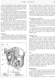
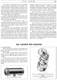
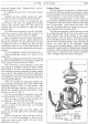
Slow Running Adjustment
The stop screw
19
(Fig.
6)
determines the speed
of
slow running. To increase
the
slow running speed, the
stop screw must be turned
in
a clockwise direction.
If
turned anti-clockwise, a slower "tick-over" will be
obtained.
The richness
of
the slow-running mixture is con-
trolled by the air-regulating screw
17. Should the engine
refuse to
"tick"
over for any length
of
time
or
stall
on
deceleration, the slow running
jet
18
may be choked and
should be cleaned. After examination re-set the slow
running by means
of
the throttle stop screw and the air
regulating screw.
If
the engine is inclined to hunt when
running slowly the mixture is too rich
and
must be
weakened
by
turning the air regulating screw
in
an
anti-
clockwise direction. The best position for this screw,
from the point
of
view
of
pick up, is within three turns
of
the full home position. Check by speeding up the
engine and releasing the accelerator pedal quickly.
If
the engine stalls, the slow running adjustment is
not
correct
and
the idling speed should be slightly increased
to a point where the sudden release
of
the throttle after
accelerating allows the engine to settle to
an
even
"tick
over".
Do
not
expect a new engine which is
tight in its bearings to idle perfectly.
It
must be borne
in
mind
that
factors other than the
carburetter such as
non
air-tight joints, worn valve
guides, valves
not
seating, ignition too far advanced and
incorrect setting
of
sparking plug gaps can have con-
siderable influence on
"slow running" when the engine .
is
out
of
gear with the
car
stationary. Such details
should always be given consideration when the slow
running is irregular. The carburetter alone should not
be suspected.
General
Swill
out
the bowl
of
the carburetter occasionally
with clean petrol to remove any sediment
that
may be
present.
Under normal conditions no other attentions
or
adjustments should be necessary. Once correctly set,
many thousands
of
miles
of
satisfactory running should
be obtained.
Should the car be used
in
very
hot
climates
or
at very
high altitudes, a slightly weaker setting may be used, or,
alternatively,
if
used
in
very cold climates, larger jets
may be necessary.
Advice on this question will readily be given on
application to Service Department,
or
the Zenith
Carburetter Co. Ltd., Honeypot Lane, Stanmore,
Middlesex.
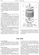
SPORTS
S.U.
CARBURETTERS
General Description
Twin
S.
U. carburetters, inclined at
an
angle
of
20
degrees to the horizontal, are fitted to the Sports. There
is
only one
jet
per carburetter and the fuel flow through
this
jet
is regulated by a needle (model EK). The piston
employed to move the
jet
needle
is
controlled
by
a
hydraulic damper.
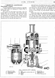
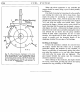
Working Description
Fuel
from the
pump
enters the float chamber cap
at
the banjo type union (A), Fig.
8.
Passing through the strainer (B) the fuel flows to
the valve opening
(C). The valve needle
is
forced down
allowing the fuel to fill
the
float chamber. The float
rises
on
its guide pin and shuts off the fuel supply by
pushing the valve needle back
on
to its seating.
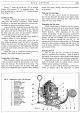
The fuel now continues to flow from the float
chamber to the union (F),
then
passes
on
to the main
jet
(G).
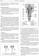
Controlling the fuel supply through this
jet
is a
tapered needle
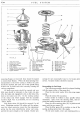
(H), see also Fig.
9,
which is secured to
the piston (I). The head
of
the piston is flanged and
grooved to form a suction disc (J).
Suction from the inlet manifold, controlled by the
butterfly throttle, causes the piston to travel upwards
or downwards, thus the needle at its tapered end controls
the supply
of
fuel drawn through the
jet
(G).
A hydraulic damper
(K)
is fitted to the piston
chamber. This damper has the effect
of
restraining
the upward movement
of
the piston
on
acceleration and
so giving a slightly enriched mixture.
Main
jet
adjustment is determined by the nut (M);
see notes
on
adjustment.
For
choking when first startil).g up, the main
jet
is
moved downwards by
the
lever (L) which
in
its
turn
is cable operated by the
knob
on the fascia. With the
throttle opened slightly a richer mixture is obtained.
Once the choke control is released
and
the throttle
operated for running, the
jet
returns to its seat and the
needle and piston resume control
of
the fuel supply.