
Owners Manual

C/10
FUEL
SYSTEM
entire fuel feed system,
as
this complaint is caused by
foreign matter in the petrol. Unless this is done
the
trouble is likely to recur.
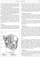
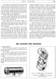
Hydraulic Piston Damper
This is a device located
in
the hollow piston rod and
attached to the oil cap nut.
It
consists
of
a plunger with
a one-way valve and its function is to give a slightly
enriched mixture by preventing the piston from rising
too quickly on acceleration.
The only attention necessary is to keep it supplied
with thin oil. See
"Regular Attentions".
Piston
The suction piston comprises the piston, forming the
choke, the needle and the suction disc. Into this assembly
is inserted the hardened
and
ground piston rod which
works in the bearing
of
the suction chamber. The piston
rod running in the bearing is the only part which is in
actual contact with any other
part-the
suction piston
and needle having clearance
fit-and
consequently
should
not
cause sticking.
If
this does occur the
whole assembly should be carefully cleaned and
the
piston rod only should be lubricated with a spot of
thin oil.
A sticking piston can be ascertained in a
few
seconds
by
inserting a finger
in
the air intake and lifting the
piston. The piston should come up quite freely and fall
right on to its seat when released.
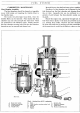
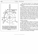
Centring the
Jet
Should
it
be essential
to
remove the jet, this can be
done by unscrewing the
jet
holding screw, see Fig.
10.
It
must be understood
that
the needle is very nearly
as
large
as
the jet, and yet must not touch it.
When reassembling
it
is necessary to carefully
centre the
jet
to the needle by adopting the following
procedure:-
First remove the pin
at
the base
of
the jet, attaching
the jet head
to
the
jet
operating lever. Withdraw the
jet completely and remove the adjusting
nut
and adjust-
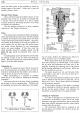
B
H70, 24.
B.
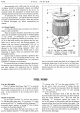
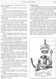
Fig. 9. Showing
the
two
forms
of
tapered
needle.
A.
Square
shoulder. B.
Tapered
shoulder.
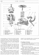
Fig. 10.
Sectional view
of
the jet.
1.
Tapered
needle.
2. Spring.
3.
Brass washer.
4.
Jet
holding
screw.
5.
Cork
gland washer.
6.
Jet.
7.
Jet
head.
8.
Top
half
of
jet
bearing.
9.
Bottom half
of
jet
bearing.
10.
Adjusting
nut
spring.
11. Adjusting
nut.
ing nut spring. Replace the adjusting nut, without its
spring, and screw up to its highest position.
When this has been done, feel
if
the piston is per-
fectly free by lifting
it
up with the finger.
If
not, slacken
the jet screw and manipulate the lower part
of
the
assembly, including the projecting
part
of
the bottom
half jet bearing, adjusting
nut
and
jet
head. Make sure
that this assembly is
not
loose.
The piston should now rise and fall quite freely
as
the needle
is
now able
to
move the jet into the re-
quired central position.
Now the jet screw should be tightened and a check
made to determine that the piston is quite free.
If
it
is
found not to be so, the
jet
screw should be slackened
and the operation repeated.
When complete freedom
of
the piston is achieved
the
jet
adjusting nut should be removed, together with
the jet, and the spring replaced. The adjusting nut
should then be screwed back to its original position.
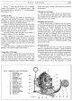
Adjusting the Carburetters
To make a thorough
job
of
adjusting twin S.U.
carburetters it is advisable to check, first
of
all, tappet
clearances, plug gaps and distributor gap to ensure that
these agree with the information given in other relative
sections within this manual.
The carburetters should then be inspected to see
that the pistons are perfectly free and that the jets are
correctly centred.