
Owners Manual

C/12
FUEL
SYSTEM
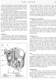
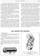
Approximately every 5,000 miles the oil bath type
of
cleaner should be dismantled, cleaned and refilled
with new oil to the level indicated by the arrow.
In
countries where the atmosphere
i&
heavily dust laden,
cleaning should be carried out
at
more frequent intervals.
To dismantle the oil bath simply release the wing
nut on top
of
the cleaner. Lift out the wire wool strainer
from the oil bath and rinse in petrol. Allow this strainer
to become thoroughly dry before reassembling the
cleaner.
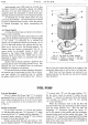
Air Cleaner (Sports)
A Vokes dry element type air cleaner and silencer is
fitted to each Carburetter.
These air cleaners should be dismantled every 2,000
miles and the elements tapped gently or brushed lightly
on the outside.
If
compressed air is available the
element can be effectively cleaned by directing a
jet
of
air on to the inside surface, thus blowing the dust par-
ticles out of, and
not
into, the filtering material.
An
element
that
has become contaminated with oil or
grease should be thoroughly washed in petrol and
allowed
to
dry before being replaced. Note: new
elements should be fitted every
10,000 miles or more
frequently in regions where an excessively dust laden
atmosphere prevails.
Access to the air cleaner elements is gained by first
removing the set screw and pulling off the top cap. The
elements can now be extracted from the perforated
cylinders for inspection and cleaning.
To remove the front air cleaner complete, disconnect
the breather pipe by slackening its clip
at
the air cleaner
and, then unfasten the supporting stay by undoing
the setpin, washer and
nut
at
the silencer base. Remove
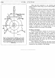
Fig. 13. The Sports air cleaner exploded.
I.
Setscrew.
2.
Washer.
3.
Top
cap.
4.
Felt pad.
5.
Element.
6.
Perforated cylinder.
7.
Felt pad.
8.
Bottom cap.
9.
Joint.
the two nuts and washers that hold the air cleaner to the
carburetter flange when
it
will be free to be lifted clear.
Both front and rear silencers are removed in an
identical manner save that the rear one has no breather
pipe connection.
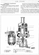
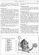
FUEL
PUMP
Type
and
Description
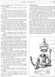
The A.C.-Sphinx Fuel Pump,
Type"U",
is
operated
mechanically from an eccentric on the engine camshaft.
The normal working pressure
is
1 t to
2t
lbs. per square
inch. A clear impression
of
the working parts is given
in Fig.
14.
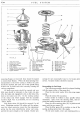
Method
of
Operation
As
the engine camshaft
"8"
revolves the eccentric
"9"
lifts the pump rocker arm "10" pivoted
at"
11" which
moves the pull
rod"
14" together with the diaphragm
"5"
downward against pressure
of
spring
"6",
thus creating
a vacuum in the pump chamber
"16".
Petrol is drawn from the tank and enters
at
"20"
into the sediment chamber
"17"
through the filter gauze
"I",
suction valve
"19"
into the pump chamber "16".
On the return stroke the spring
"6"
pushes the dia-
phragm
"5"
upwards, forcing petrol from the chamber
"16"
through the delivery valve
"4"
and opening
"3"
to the carburetter.
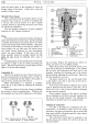
When the carburetter bowl is full the float will
shut the needle valve, thus preventing any flow
of
petrol
from the pump chamber
"16". This will hold the
diaphragm
"5"
downward against the spring
"6"
and
it
will remain in this position until the carburetter
requires further petrol and the needle valve opens. The
rocker arm
"1 0" operates the connecting link by making
contact
at"
12" and this construction allows idling move-
ment
of
the rocker arm when there is no movement
of
the fuel pump diaphragm.