
Owners Manual

FUEL
SYSTEM
C/13
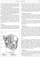
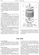
Spring
"7"
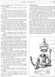
keeps the rocker arm "10" in constant
contact with eccentric
"9"
to eliminate noise. The
hand priming lever
is
indicated at "15" and the sediment
drain plug at
"18".
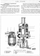
Cleaning the Filter
The filter (see Fig.
16)
should be examined every
1,000 miles and cleaned
if
necessary. Under extreme
conditions
of
dust-laden atmosphere this mileage inter-
val should be reduced
as
conditions dictate.
Access to the filter
is
gained by removing the dome
cover, after unscrewing the retaining screw, when the
filter gauze itself may
be
lifted off its seating. Remove
the drain plug and clean
out
the sediment chamber.
Clean the filter gauze in air
jet
with petrol.
The cork washer under the filter cover should be
renewed
if
broken or
if
it
has hardened.
When refitting the cover make certain that the
fibre washer
is
replaced under the head
of
the screw.
Tighten the filter cover retaining screw just sufficiently
to make a petrol-tight joint. Over-tightening will either
destroy the cork washer, crack the cover, or fracture the
main casting.
Check the pump to crankcase mounting bolts for
tightness; also check the petrol pipe unions.
Testing while on the Engine
With the engine stopped and switched off, the pipe
to the carburetter should be disconnected at the carbu-
retter end, leaving a free outlet from the pump. The
engine can then be turned over by hand, when there
should be a well defined spurt
of
petrol at every working
Fig. 14. Diagrammatic section of the fuel pump.
1.
Gauze filter.
2.
Cork sealing washer.
3.
Delivery union.
4.
Delivery valve.
5.
Diaphragm.
6.
Diaphragm spring.
7.
Anti-rattle spring.
8.
Camshaft.
9.
Camshaft eccentric.
10.
Rocker arm.
11.
Rocker arm pivot.
12.
Connecting link.
13.
Priming lever cam.
14.
Diaphragm pull rod.
15.
Priming lever.
16.
Pump chamber.
17.
Sediment chamber.
18.
Sediment drain plug.
19.
Suction valve.
20.
Inlet union.
stroke
of
the pump, namely, once every two revolutions
of
the engine.
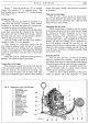
Removing from the Engine
First the pipe unions should be disconnected;
the two nuts fixing the fuel pump to the engine crank-
case should then be unscrewed, after which the fuel
pump will come away readily.
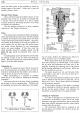
Dismantling the Fuel Pump
Before commencing to dismantle clean the exterior
of
the pump and make a file-mark across the two flanges
for guidance to facilitate reassembly in the correct
relative positions. After separating the two main
castings dismantling
of
the remaining components
associated with each,
is
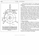
quite straightforward. The dia-
phragm and pull
rod
assembly can be withdrawn by
first
of
all turning
it
through
90°
(see Fig.
17).
No
attempt should be made to separate the four diaphragm
layers from their protector washers and pull rod,
as
this
is, at all times, serviced
as
a complete assembly, being
permanently riveted.
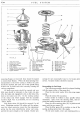
Inspection of
Parts
First all parts
(see
Fig.
15)
must be thoroughly
cleaned to ascertain their condition. Wash all parts in
the locality
of
the valves in a clean paraffin bath separate
from that employed for the other and dirtier components.
Diaphragm and pull rod assemblies should nor-
mally be renewed, unless in entirely sound condition
without signs
of
cracking
or
hardening.
Upper and lower castings should be examined for
cracks or damage and
if
the diaphragm or engine