
Owners Manual

FUEL
SYSTEM
C/15
previously detailed under "Cleaning Filter" and de-
tailed on page C/13.
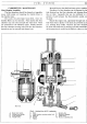
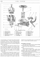
To assemble the lower half
of
the pump, proceed
as
follows:-
Assemble link (22), packing washers (19), rocker
ann
(20)
and rocker arm spring
(21)
in
the body
(16).
Insert the rocker arm pin
(17)
through the hole
in the body, at the same time engaging the packing
washers, link, and the rocker arm; then spring the
retaining clips into the grooves on each end
of
the
rocker arm pin.
The rocker arm pin should be a tap fit in the body,
and if, due to wear, it
is
freer than this, the ends
of
the
holes in the body should be burred over slightly.
Note. The fitting
of
the rocker arm pin can be simpli-
fied by first inserting a piece
of
. 240-in. diameter
rod
through the pin hole in one side
of
the body far enough
to engage the rocker arm washers and link, and then
pushing the rocker arm pin in from the opposite side,
removing the temporary rod as the pin takes up its proper
position.
To fit the diaphragm assembly to the pump
body:-
Place the diaphragm spring
(23)
in position in the
pump body.
Place the diaphragm assembly (24) over the spring,
the pull
rod
being downwards, and centre the upper end
of
the spring in the lower protector washer.
Press downwards on the diaphragm
at
the same
time turning the assembly
to
the left in such a manner
that the slots in the pull rod will engage the fork in the
link, ultimately turning the assembly a complete quarter
turn to the left. This will place the pull
rod
in
the proper
working position in the link and,
at
the same time, permit
the matching up
of
the holes
in
the diaphragm with those
on the pump body flanges.
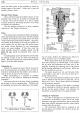
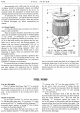
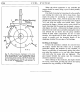
When first inserting the diaphragm assembly into
the pump body, the locating
"tab"
on the outside
of
the
diaphragm should be at the
11
o'clock position. After
turning the diaphragm assembly a quarter turn to the
left the
"tab"
should be at the 8 o'clock position. These
positions are shown in Fig.
17.
The two sub-assemblies
of
the pump are now ready
for fitting together, and this is carried out as
follows:-
Push the rocker arm (20) towards the pump until
the diaphragm
is
level with the body flanges.
Place the upper half
of
the pump into the proper
position as shown by the mark made
on
the flanges
before dismantling.
Install the cover screws and lock washers, and
tighten only until the heads
of
the screws just engage
the washers.
Release and push the rocker arm away from the
pump so as to hold the diaphragm
at
the top
of
the
stroke and, while
so
held, tighten the cover screws
diagonally
and
securely.
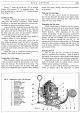
Testing the Pump
The best method is
by
using an A.C.-Sphinx bench
test stand, on which the suction side
of
the pump
is
piped
to a tin
of
paraffin at floor level
and
the outlet side
of
the
pump connected to a stop tap
and
pressure gauge.
First flush the pump through to wet the valves and
seats,
and
then completely empty it again by continuing
to operate the rocker arm by hand with the suction pipe
clear
of
the paraffin. Again operate the pump.
Not
more
than
20
strokes should be necessary to secure de-
livery
of
paraffin from the pump outlet.
With the same apparatus a second test can be made
by working the pump with the
tap
on
the delivery side
closed, pressure then being recorded on the gauge.
After ceasing to work the pump
it
should take several
seconds for this pressure to return to zero, thus denoting
that the valves are seating properly. Also, while there
is
pressure, the outer edge
of
the
diaphragm-visible
between the two clamping flanges-should be carefully
examined for leakage and the retaining screws tightened
if necessary. When working a pump by hand a somewhat
longer stroke is obtained and the pressure developed
is
apt to be higher than when fitted to the engine.
i-
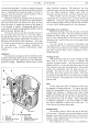
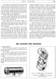
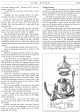
Fig. 16. Fuel pump top cover exploded.
I.
Top
cover screw.
4.
Gauze filter.
2.
Top
cover.
5.
Inlet union.
3.
Cork
sealing washer.
6.
Drain
plug.
7.
Outlet union.