
Owners Manual


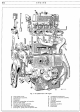
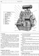

ENGINE
D/3
Connecting Rods
The connecting rods are
of
"H"
section steel
stampings and employ detachable
"Thinwall" bearings,
the caps
of
which are secured by two H.T. steel bolts.
The small end
is
fitted with a clamping bolt to secure the
gudgeon pin. Torque wrench loading for connecting
rod nuts
33
lbs. ft. (4.
562
kgm.).
Gudgeon
Pin
Of
tubular section, the gudgeon pin is grooved to
take the connecting
rod clamping bolt.
At
70°F,
(21. 1 °C.) the pin should be a push
fit
into the piston boss.
Pistons
The split skirt type pistons are
of
aluminium alloy
with anodised finish and the lower ring groove is drilled
for oil return.
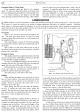
Piston Rings
The two compression rings and one oil control ring
are situated above the gudgeon pin.
Ring gap
.008-.012-in. (.2032-.3048 mm.)
Groove
width:-
Compression... . 095-. 095!-in. (2. 413-2.4257 mm.)
Oil Control
....
1577-.1582-in. (4.0055-4.0182 mm.)
Groove
Clearance:-
Compression... . 0012-. 0027-in. (. 0304-.0685 mm.)
Oil Control .. . . 0025-. 0030-in. (. 0635-.0762 mm.)
The latest models have four ring
pistons-1
plain,
2 taper and 1 oil control.
Camshaft
Three white metal lined steel shell bearings support
the one-piece forged steel camshaft on the left-hand
side
of
the engine. Chain driven from the crankshaft,
the camshaft incorporates a spiral gear to drive the oil
pump and distributor shaft, and an eccentric cam for
operating the fuel pump. The end float
of
. 002-. 008-in.
(. 0508-. 2032 mm.) is controlled by a bronze flange
at
the rear
of
the camshaft gear. The camshaft drive
employs a patent tensioned gear with Duplex roller
chain, . 375-in. (9.
525
mm.) pitch,
52
pitches.
Overhead Valves
The inlet valve is
of
Silicon Chrome Steel and the
exhaust
of
XB
steel. Each valve has a single coil spring
retained by a cup and split cone cotters, the latter being
grooved externally to locate a safety clip. Both inlet
and exhaust valves have a seat angle
of
45
deg. whilst
the
seat width
of
the inlet valve is {
6
-in. (1.
5875
mm.)
and the exhaust valve
i-in.
(3
.175 mm.). Valve guides
are fitted having a stem clearance
of
.0015 to .0025-in.
(.
0381
to .
0635
mm.) for the inlet and . 0015 to . 0019-in.
(.
0381
to . 0482 mm.) for the exhaust valves.
Valve
Gear
Tappets and push rods operate bushed rockers on a
hollow shaft with
an
adjusting screw for valve clearance
on each push rod end.
Side play
of
the rockers
is
con-
trolled
by
four coil springs.
Valve Timing
Both the crankshaft gear and the camshaft gear are
spot marked for valve setting; the inlet valve opens
5 deg. before
T.D.C.
The inlet valve
of
No. 1 cylinder must be timed to
open
5°
before top dead centre, the equivalent
of
which
on the flywheel
is
a point !-in. (1.
27
em.) before T.D.C.
on a diameter
of
11/
6
-in. (28.
7337
em.), tappets being
set to .
021-in. (.
5334
mm.) before testing. These should
be re-adjusted to .
015-in. (.
381
mm.) afterwards for
normal running.
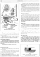
Flywheel
The flywheel, which has a diameter
of
11
ftr-in.
(28.
7337
em.), is bolted to the crankshaft flange and
the starter ring
is
of
hardened steel with
117
teeth, the
diameter over the teeth being 11. 786-in. (29. 9364 em.)
and
is
shrunk on to the flywheel.
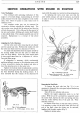
Induction and Exhaust Manifolds
The induction and exhaust manifolds
of
the Saloon
model range are separate castings. They are bolted
together
at
a central flange,
at
which point a special
design
of
"hot
spot" is incorporated. The combined
assembly is attached to the monobloc by clamping
washers, studs and nuts.
When assembling the manifolds to the cylinder head,
the point is stressed that the manifolds should be pulled
up tight to the head before tightening the common
central flange bolts; this avoids the possibility
of
distortion.
In
respect
of
the Sports there is no common induc-
tion manifold or
"hot
spot". Each
of
the twin carburet-
ters feeds direct to the cylinder head through junction
pipes which are secured in place by the inner nuts and
clamping washers
of
the exhaust manifold studs. These
two junction pipes are connected to each other
by
a
single pipe, fitted to balance the gas pressure in the
inlet ports.
The exhaust manifold is a three way pipe with the
centre pipe being the larger and covering two exhaust
ports.
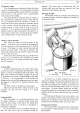
Lubrication System
The forced feed lubrication is provided by a spur
gear pump, situated in the sump, and driven by a vertical
shaft from the camshaft.
Oil is drawn through a strainer
in the sump and forced under pressure
to
the main,
big-end, camshaft and the valve rocker shaft bearings.
An
external by-pass filter is fitted on the right-hand
side
of
the engine.
The crankcase
is
vented to the atmosphere in the
engine side cover.