
Owners Manual


ENGINE
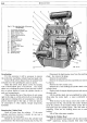
D/7
SERVICE OPERATIONS
WITH
ENGINE IN POSITION
Valve Mechanism
The
overhead valve operating mechanism
of
this
engine is
of
normal
design, incorporating
an
oil feed
under pressure from the
main
oil gallery to the rocker
shaft, from which oil passes to each rocker
and
its
adjusting screw.
The complete rocker gear can be removed for
examination without releasing the cylinder head.
The
valve rocker cover should first be removed
and
then the
oil feed disconnected. This is followed by the removal
of
the nuts
and
washers holding each rocker shaft bracket
to
the
cylinder head.
The
complete assembly
can
now be
removed. Replacement is a reversal
of
the above
procedure.
Adjusting the Valve Clearance
Lift the valve cover after removing the air cleaner
and
two special cap nuts. Between the rocker
arm
and
the valve stem there
must
be a clearance
of
. 015-in.
To
check this adjustment have the engine turned by
the starting handle
and
note
the
point
at
which
the
push
rod
stops falling.
From
this
point
until
it
starts
to move again there
must
be
a clearance
of
.015-in.
Test with feeler gauge.
If
adjustment is necessary, whilst continuously
applying sufficient pressure
to
the
adjusting screw with
a heavy screwdriver, slacken the locknut
and
raise
or
lower the adjusting screw in the rocker arm.
Tighten the
locknut
when the adjustment is correct,
but always check again afterwards
in
case the adjustment
has been disturbed during the locking process.
It
is
most advisable
that
this recheck
of
the clearance be
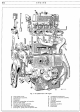
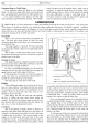
Fig.
6.
Vah'e adjustment.
A.
Screwdriver.
B.
Feeler gauge, .015-in. thick.
made
while the engine is
at
normal
working temperature.
In
replacing the valve cover take care
that
the
joint
washer, using a new one
if
necessary, is properly
in place to ensure
an
oil-tight
joint
and then refit the
air cleaner.
D
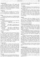
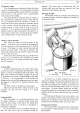
Fig.
7.
Removing a push rod.
A. Tappet adjusting screw.
B.
Valve spring.
C. Screwdriver. D.
Valve rocker.
Removing the Push Rods
To
remove the push rods (see Fig.
7)
it
is
not
necessary to dismantle the valve gear beyond slackening
the
tappet
adjustment.
Take off the two cylinder side covers.
Slacken
the
tappet
adjustment screw to its full
extent.
With
the aid
of
a screwdriver, supported under
the rocker shaft, depress
the
valve and spring
and
then
slide the rocker sideways free
of
the push rod. With-
draw the push rod.
In
respect
of
the front
or
rear
end rocker, however,
it
is necessary to take
out
the split cotter
pin
from the
end
of
the shaft, when
the
rocker can be removed,
together with
the
plain washer (Fig. 7).
Replace
in
reverse order.